background image

SAFETY INFORMATION 

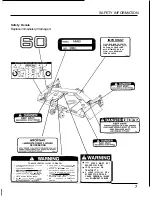
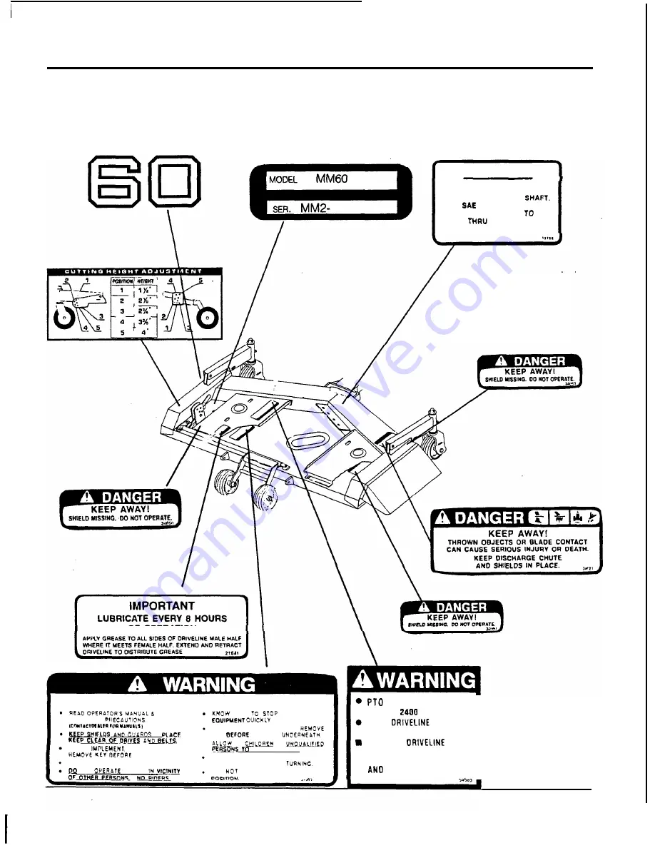
Safety  Decals 

Replace immediately 

if 

damaged. 

IMPORTANT 

FILL  GEAR  BOX TO  CENTER 
LINE 

OF 

HORIZONTAL 

USE 

90 

GEAR  LUBE. 

ALLOW 

TIME 

FOR  OIL 

FLOW 

BEARINGS. 

THEN  RECHECK. 

OF 

OPERATION 

TO  AVOID 

SERIOUS  INJURY 

OR 

DEATH! 

SPEEO 

MUST  N O

FOLLOW 

now 

TRACTOR  AND 

EXCEED 

RPM. 

LOCK 

ON 

KEY 

WORKING 

TRACTOR  PTO. 

ALL SAFETY 

BLOCK  UP 

IMPLEMENT 

AND 

IN AH EMERGENCY. 

LOWER 

STOP 

ENGINE 

AND 

BE 

CAREFUL  ON  UNEVEN  TERRAIN. 

CLEAR  MOWING AREA 

OF 

DEBRIS. 

DECREASE  SPEED  WNEN 

CAUSE  PERSONAL  INJURV 

NOT 

MOWER 

DO 

OPERATE  I N   TRANSPORT 

EQUIPMENT  FAILURE. 

NO 

OH 

LOOSE 

OR  A 

RUN  EOUIPMENT. 

DISMOUNTING. 

HIGHER 

PTO  RPM  CAN 

... 

Summary of Contents for MM60

Page 1: ......

Page 2: ......

Page 3: ...y Mower Recordthe serial number of your mower Serial Number see Safety Decal pagefor location Providethis informationto your dealer to obtain correct repair parts Throughout this manual the term NOTICE is used to indicatethat failure to observe this instructioncan cause damage to equipment The terms CAUTION WARNING and DANGER are used in conjunctionwith the Safety AlertSymbol atrianglewith an excl...

Page 4: ...able to your particular situation The illustrationsand data used inthis manualwere current at the time of printing but due to possible in lineproductionchanges your machine may vary slightly in detail We reservethe right to redesignand change the machine as may be necessarywithout notification 1 Some illustrations in this manual show the mower with safety shields removed to providea better view Th...

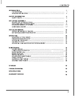
Page 5: ...ACTOR 21 DETACHINGMOWER FROMTRACTOR 25 OPERATION 28 ADJUSTING CUlllNG HEIGHT 29 PRE OPERATIONCHECK LIST 30 OPERATINGTECHNIQUE 31 CUlllNG PATTERNS 32 OPERATINGYOUR MOWERWITH OTHER EQUIPMENT 33 MAINTENANCE 36 OWNER SERVICE 36 LUBRICATIONINFORMAllON 37 BLADEINSPECTION 38 BLADESERVlClNG 39 REPLACINGBELTS 41 DEALER LEVELMAINTENANCE 42 SPINDLEREPAIR 43 UNIVERSALJOINT REPAIR 47 GEARBOX MAINTENANCE 49 STO...

Page 6: ...eratedwithin the limitations explainedin this manual Training Safety instructionsare important Readthis manual the tractor manualand all safety rules Knowyour controls and how to stop tractor engineand mower quickly in an emergency Operators must be instructedin and be ca pableof the safe operationof the equipment its attachmentsand all controls Do not allow anyone to operate this equipmentwithout...

Page 7: ...ch or brake pedal mechanismsare improperly adjusted allowingthem to contact mower components instructed in this manual properlyadjusted clutchand brake pedal mechanismswill not contact mower components You should frequently checkthat the tractor clutch and brake pedal mechanismsare in adjustment If the clutchor brake pedal mechanisms can contact mower components do not operate until properly adjus...

Page 8: ...ractor enginerunning Beforeworking underneath raise mower install transport lock and block mower securely Hydraulicsystem leak down and failure of mechanicalor hydraulic system can cause equipmentto drop Keep a l l persons away from operator control area while performingadjustments service or maintenance sharp free of nicks and cracks and securely fastened Use a new Nylok blade bolt when you repla...

Page 9: ...AND GUARDS m PLACE KEY DEFORE WORKING UHOERNEATN TRACTOR PTO I C I I C I w LtPr rn IY I ALL SAFETY PI4ECAUTIONS UEEP_UELR W D_RIVU AH0 9CLIS BLOCK UP IMPLEMENT AND HEMOVE EOUIPMENT OUICKLV IN AH EMERGENCY LOWER IUPLEMENL STOP ENGINE AND BE CAREFUL ON UNEVEN TERRAIN CLEAR MOWING AREA OF DEBRIS DECREASE SPEED WNEN WRNING CAUSE PERSONAL INJURV P a NOT OPERaTE MOWER IN V I C W DO NOT OPERATE IN TRANSP...

Page 10: ...tion easy Referto illustrations accompanying text parts lists and explodedview drawings For all pins shafts and other bearing surfaces lubricate bearingareawith a lithium basedgrease of 2 consistency with a MOLY molybdenum disulfide additive before installing The manual will also indicate when grease is necessary Always wear relatively tight and belted clothing to avoid entanglement in moving part...

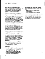
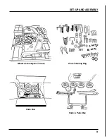
Page 11: ...SET UP AND ASSEMBLY Mower Assembly Kit in Crate Parts Box Parts in Burlap Bag Parts in Parts Box 9 ...

Page 12: ...eal 5 Checkthat gearbox is serviced and that vent plug is properly installedand seals are not leak ing 6 Checkthat blades have been properlyinstalled Delivery Check List Dealer Responsibility 1 Check mower attitude and belt alignment 2 Checkthat mower lift is properlyadjusted See Assembly instructions 3 Show customer how to make adjustments 4 Explainimportanceof lubricationto customer and point ou...

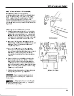
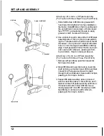
Page 13: ...edflange on lift plate assembly will face rear of tractor InsertY lift bracketso that fork of Y faces front of tractor 3 Attach mower lift plateassemblyto tractor passing the two projectingstud bolts on the transmission housingthrough the holes in the lift plateflange Slide on 2 spacers previously removedand handtighten both26 mmflange locknuts 4 Reach beneaththe mower lift plateassembly and caref...

Page 14: ...nd lift link untilthey align Insertgreased22 mmx 76 mm clevis pin and secure with cotter pin passing pinfrom top to bottom Headon clevis pin faces in Attaching Lift Link to Lift Plate Assembly For Tractors With Rear Three Point Hitch 1 Remove left handthree point hitch lower link from lower link shaft 2 Mount lift link and lower link back on lower link shaft by lining up middle hole in lift link a...

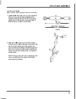
Page 15: ...arrel I I I 365 mm I c 14 4 in I y I I I with loader subframe I I Y 375 mm 14 8 in y 2 Slide eye of liftrod over pin on tractor lift arm Positionclevis of lift rodbetweenbracketson lift link Notethat outside legof liftrodgoes out side of lift link as illustrated Installwith greased 22 x 76 mm clevis pinwith headon left side as shown Secure both endswith 22 rnrnwashers andlinchpins NOTE The eye of ...

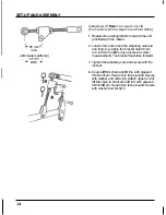
Page 16: ...ting nuts and turn them to position the brackethole 85 mm 3 4 in from the lift rod eye center to center measurement The bracket must face forward 3 Tighten the adjusting nuts and secure with the locknut 4 Couple lift link chain and lift link with greased 16 mm lift pin Headof pin faces inward Secure with washer and cotter pin Attach upper end of lift link chainto bracketon lift rod with greased 16...

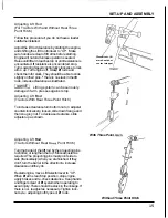
Page 17: ... stop Adjusting Lift Rod Tractors With Rear Three Point Hitch To increaseclearanceturn bottomnut on adjuster counterclockwiseto loosen slide downflangeand then snugtop nut To decrease clearance slide adjuster up as shown Adjusting Lift Rod Tractors Without Rear Thtee Point Hitch Turnthe barrelof the lift rod bythe projectingpins to shorten or lengthenthe rod Moveadjuster as required The projecting...

Page 18: ...ng Front Link Bracket to Tractor 1 Frombottom slip the assembledfront mount ing bracketup onto the front frame rails 2 Insert 8 flange bolts 12 mmx 30 mm Tightenall to 6 kg m 43 ft lb NOTE With pins correctly installed they will face rearwardanddownward when front link bracketis installedon the tractor Assembling Rear Link Bracket Insertthe greased rear quick releasepin in the mountingbracket atta...

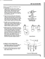
Page 19: ...r over mower They cannot be rotatedforward after tractor is above mower deck Mowerdriveline and U jointshould be on top of stabilizer bar not caught below it Be sure the left rear deck link is installed with the side marked UP facing top Rear Mower Deck Links Installing Deck Hooks Rightand left mower deck hooks are installed on brackets in the front center of the deck See position as indicated Scr...

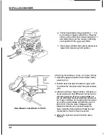
Page 20: ...uge wheel arm Securewith flanged locknut Tighten locknut so that sides of brackettouch wheel sleevewithout binding Do notover tighten Repeatfor opposite side 3 Raisefront and rear wheels to middle position insert pin in center hole of adjustment bracket Cuttingheightwill be2 75 in Levelthe mower ta assure proper cut Moweralso needs slight forward tilt If adjustingwheels and blade height after inst...

Page 21: ...hts is approximately5 mm 1 4 in Do not replace split pin untilafter adjusting forward tilt 4 Adjust forward tilt by measuringfrom front and rear of bladesto ground The front of the blades should be about 10 mm 3 8 in lower than the rear of the blades If differenceis less than 5 mm 1 4 in take washers from bottom of gauge wheel shaft and moveto top If difference in bladetip to ground measurementsis...

Page 22: ... Installing Gear Box Oil and Vent Plug Gearbox is shippedWITHOUT oil Plastic gearbox vent plugcomes in burlap bagwith other mower assembly parts 1 1 Before operating mower check gearbox and fill if necessary with SAE 9OW gear lube Operating without oil will severely damage gearbox 1 Remove level plug 2 Add oil until it seeps out level plug hole 3 Allow several minutesfor oil to flow through bearin...

Page 23: ... right and left links Securewith 16 mm greased clevis pin insertingpin from out side Insert linchpinto lock Front Mower Links INSTALLING MOWER TO TRACTOR 1 Adjust gauge wheels to lowest cutting position 2 Chock right and left front wheels as shown 3 Start the tractor and keep engine at low idling speed Set the liftcontrol lever to the UP positionand keepthe lift arm up Drive front wheels over the ...

Page 24: ...tting position 2 in 2 Rollthe deck forward or backward right or left to positionthe rear links under the quick release pins 3 Attach the left rear mower linkfirst Pull back on quick release pin then liftmower link by handto the frame brackets If holes in rear linkdo not line up with frame bracket adjust the positionof the mower untilthey do Keepingthe holes lined up pull the quick release pin towa...

Page 25: ...d throughthe holesinsidethe frame bracket Attaching Driveline to Mid PT0 1 Engineshould be OFF with key removed before attaching U jointto Mid PTO NOTE The mower drive shaft is a 2 piece assem bly The inner shaftcan be removedfrom the outer shaft They fit together inonly one way A red paint dot on each section marks the blind spineswhich must be aligned 2 Set the PTO Selector to the REAR position ...

Page 26: ... so gauge wheels liftoff the ground at the same time Checking Mower Lift With Loader Sub Frame Installed 1 If you have a front loader sub frame installed you must use the following procedure to adjust the mower linkage to avoid damage to the deck or linkage i 1 Slowly movethe Lift Selector Leverto the UP positionto raisethe deck Immediately lower the deck at the first indicationof resistance 2 Che...

Page 27: ...olds in slot infront link bracket Holdfront link and lower it to ground Repeat for other side Mower deck will descend when front links are released Keep fingers and feet from being caught below the mower to avoid injury Detaching Rear Links 1 Pulllocking pinon left rear link and draw it towardsyou to remove If rear link cannot be detachedeasily shake the mower back and forth with foot until rear l...

Page 28: ...ree it 3 Makesure that U joint is placedwhere it will not be crushed by tractor tires when tractor is backedover pulleycovers UflArm Lift Arms Fasten to Mower Deck Detaching Lift Joints when pulling pins as mower deck may drop slightly 1 Pullpinsattaching liftjoints to lift plates brack 1 Keep fingers clear of brackets ets as illustrated NOTE If hydraulic lift system is notfully down pins may be u...

Page 29: ...dels select 4 wheel drive 3 Move LiftSector Lever to UP and raise lift armsto maximum position Keepingengine at low idle speed set maintransmission to RE VERSE on 4 wheel drive models move selec tor to 4 wheeldrive position 4 Makingfine speed adjustmentswith accelera tor backthe tractor off the mower with front wheels passingover pulleycovers NOTE Make sure that the wheels pass over pulley covers ...

Page 30: ...eavy weed mowing It is equippedwith suction type bladesfor best results in lawn mowing Recommended mowing speed for most condi tions isfrom two to five mph 0 Do not allow children or unqualified per sons to operate equipment Keep bystanders away from equipment while it is in operation Before working underneath raise mower install transport lock and block mower securely Hydraulic system leak down a...

Page 31: ...mportantthat all three adjustments bethe same To set cutting height match numbers shown in illustration Example hole 2 in caster adjustment with hole 2 in gaugewheel adjustment etc 1 Avoid very low cutting heights Striking the ground with blades gives one of the most damaging shock loads a mower can encounter and if this occurs repeatedly it will cause damage to mower and drive Approximate Cutting...

Page 32: ...r mid Pi0 shaft it is importantthat the spring activated lockingcollar slides freely and the balls are seated in groove on mid PTOshaft 8 Check mower cutting height and attitude adjustment SeeAdjusting Cutting Height on Page 29 Mower vibration tends to loosen bolts during operation All hardware should be checked regularly to maintain proper torque It is a good practice to check mower before each o...

Page 33: ... to leave tire tracks However it is better to cut grass frequently ratherthan too short Short grass deteriorates rapidly in hot weather and invites weedgrowth during growing seasons Follow local recommendationsfor the suitablecutting height inyour area When operatingthe mower movethe LiftControl Leverto the DOWN position This will allow the mower to follow groundcon tours Tips Extremelytall materi...

Page 34: ... can mow in a neat mowing pattern Overlapping on straightaways Be sure that each mowing laneoverlaps suffi ciently The recommendedoverlapwidth is be tween 4 6 inches or approximately the width of one of the mower sfront tires Overlapping in curves and turns When cutting in curves and turns shift to a slower speed and be sure to overlapthe previous cut by 20 50 or approximately half the width of th...

Page 35: ... the engine and set Lift ControlLever to UP and raise the mower to maximumheight Turn LoweringSpeedControlfully clockwiseto lock lift arms in up position Leave Lift Control Lever in UP position Stop engine set brake and remove keys I I Make sure to turn Lowering Speed Control fully clockwise to lock hydrau lic system before attaching mower deck hook This prevents the mower deck from descending and...

Page 36: ...ing Mower Hook 1 Start engine and set Lift Control Lever on UP to raise lift arms to maximum position Turn off engine turn LoweringSpeed Controlfully clockwiseto lock hydraulicsystem and set brakes 34 2 Remove clevis pin and use fool to pull mower hookoff of lockup pin Usecaution since hook may be under pressure Mower hook may be under tension Set Lift Control Lever to UP and raise arm to take ten...

Page 37: ...olfully clockwiseto lock hydraulic systemand set brakes NOTE Block the lift plateto its full UP position 3 Pull pin from projecting bracket at top of left hand lift rod and removeas illustratedto release liftchain Holdchain so that it does not fall 4 Attach lift chain to projectingchain rest pin on the RollOver ProtectionSystem Securewith washer and cotter pin MAKE SURETO RE TAIN CLEVIS PIN IN SAF...

Page 38: ...raulic system leak down and failure of mechanicalor hydraulic system can cause equipment to drop Keep all persons away from operator control area while performing adjust ments sewice or maintenance Lower mower to ground or block securely turn tractor engine off remove key and disconnect mower driveline from tractor PTO before performing any service or maintenance b4 q Always wear relatively tight ...

Page 39: ...ere may be a small amount of lubeemittedfrom the vent plug this is not considered leakage Check lube levelevery 50 hours by removingthe vent plugand checkingthe gauge on the bottom of the vent plug The oil levelshould show 1 in on the gauge You may also check the oil by usingan Allen wrench to removethe level plug in the front of the gearbox Do not over lubricate Over fillingthe gearboxwill cause ...

Page 40: ...wear The right and center blades can be seen underthe right side of the mower deck The left bladecan be seen from under the left front edge of the mower deck Turn the blades 180 to inspect the opposite side NOTE If any of the blades show signs of damage or excessivewear a more thorough inspection is necessary A dull bladecan be sharpened but a bladethat isworn out bent crackedor otherwise damaged ...

Page 41: ...lderwasher if removed small end to lead in clockwise rotation as viewed from up Make sure blade cutting edge is positioned top of mower 3 Excessiveblade slippingcan cause cup washers to burn and losetheir clampingforce Inspectcup washers to determine if they are burned or have lost their clamping force Replaceas necessary Use a new Nylok blade bolt when you replace the blade Do not substi tute any...

Page 42: ...1 Remove blades 2 Always sharpen bothends at the same time to maintainbalance Followoriginal sharpening pattern Do not sharpen bladeto a razor edge Leavefrom 1 32in to 1 1 6in blunt edge Do not sharpenthe back side of the blade 1 When sharpening blades be sure to balance them Unbalanced blades will cause excessive vibration which can damage blade spindle bearings Vibration may also cause structura...

Page 43: ...gearbox mount to mower deck and loosenthe two boltson the rear of the gearbox mount Tip the gearbox up and slip the belt off the gearbox pulley and slide it underneaththe gearbox to completely remove Installing Blade Belt 1 Removethe two bolts holdingfront of gearbox mount to mower deck and loosen the two rear bolts if not done previously 2 Tilt gearbox up and slide belt underneath gearbox Fit int...

Page 44: ... failure of mechanical or hydraulic system can cause equipment to drop control area while performing adjustments service or maintenance Lower mower to ground or block securely turn tractor engine off remove key and disconnect mower driveline from tractor PTObefore performing any service or maintenance 9 Keep all persons away from operator Always wear relatively tight and belted clothing to avoid e...

Page 45: ... of spindle housing isthe short portion frame and remove spindle 2 To minimizewear bearingcups cones and sleevesare pressfit to shaft and will requirea press or similar device for removal 3 When disassembling support housingcasting to prevent damage 4 Remove bearingcups by placinga punch in housingslots and drivecup out Alternate punch positionsfrom side to side Usecare to prevent housingdamage 5 ...

Page 46: ...gand cups 6 Cup 7 Shaft Spindle Assembly Blade Spindle Disassembly 1 Support spindle in a press and push shaft down through housing 2 Remove seals from housing 3 Remove bearing cups from housingas de scribed in Spindle RepairTips section 4 Removebearing cone from shaft 44 ...

Page 47: ...justment is set by pressing sleeve against bearing cone until proper adjustment is attained 6 Installsleeveon shaft and presssleeve and bearing cone onto shaft untilall bearingfree play is removedand there is a slight drag similarto adjusting the front wheel bearingson an automobile Check by spinning spindle It should turn freely 6 Be careful not to over tightenbearings Proper bearingadjustment is...

Page 48: ...bricant to top seal 2 anc installwith spring up away from center of housing Top seal should be flush with top of housing 15 Lubricatespindle with a lithiumgreaseof 2 consistencywith a MOLY molybdenum disul fide additive Vent top sealwith a blunt edged tool such as a letter opener while filling with grease Rotate housingon spindle shaft checking for free movement Blade Spindle Installation 1 Insert...

Page 49: ...ss m5 3 Seal 4 Snap ring 5 Cup and bearings 6 Yoke Universal Joint Assembly Disassembly 1 Removesnap rings from insideof yokes in four locationsas shown 2 With snap rings removed support drive invise holdyoke in hand and tap on yoke to drive cup out of yoke 47 ...

Page 50: ...p with grease fiiing away from shaft Becareful notto disturb needle bearings Insertanother bearingcup directly across from first cup and press in as far as possiblewith hand pressure 2 Trap cups invise and apply pressure Be sure journal cross is started into bearings and continue pressurewith vise squeezingin asfar as possible Tap yoke to aid in process 3 Seat cups by placinga drift slightlysmalle...

Page 51: ...g operation remove plug and apply low air pressureto opening in side of plug Checkto make sure it is venting out of the top 6 Operating gearboxwith improper lube level may also cause seals to leak Also check for housingcracks If any of these conditions exist correct them clean areawhere leakagewas evident returnmower to service and check to make sure leakage has been stopped 7 Bearingmaladjustment...

Page 52: ... seats Inspectgear shafts Pay specific attentionto areas where seals seat Checkfor cracks grooves nicks or bumps Replace housing or shaft if damage cannot be repaired by resurfacingwith emery cloth 2 Lubricateseal lip and carefully guide over shaft using a blunttool such as a letter opener Be careful notto rollseal lip under Do not use a knife as it will nickand ruin seal 3 Placeseal squarely on h...

Page 53: ... 2 Positioncenterlineof driie pulley 0 98 0 030in above mounting surface of gearbox stand as shown This is a very criiical dimension and must be held Alternately tighten split taper bushingset screws to 2 kg m 14 Mbs Check mountingdistanceto make sure it is correct 1 Split taper bushing 2 Drivepulley 3 Gearbox stand 4 Key Drive Pulley Assembly 51 ...

Page 54: ... housingclean and free of accumulated grass clippings bywashing it down with a hose after use and or cleaning it with a wire brush and scraper Remove any rust and apply a rust resistant paint Cleaning and rust prevention are especially important before seasonal storage 1 Washing the deck directly after use can cause prematurebearing wear Allow the deck to cool before washing then run the deck to r...

Page 55: ... be replaced 3 Belt hung up or rubbing 3 Check belt for free travel in pulleys and belt 4 Beltor pulleysworn out 4 If belt rides in bottomof pulley groove either 1 Belt misalianedor rubbingguide 1 Re alignbelt or guide Be sure belt doesn t rub _ _ any other part while running 1 Damaaedbelt 2 Worn pulleygroove 1 Lay belt flat on floor If belt does not lie flat has humps or twists indicatingbrokenor...

Page 56: ...perateat fullthrottle Use lower speed range Set mower deck higher than desiredheight for first pass then cut to desired heighton second pass 4 Allow to dry beforecutting 5 Set mower deck higher than desired height for first pass then cut to desired heighton second pass on Mid PTO 6 Run at full throttle Do not exceed2400 rpms _ _ _ _ 1 Cutting heighttoo low 1 Increaseto proper height 2 Tractor spee...

Page 57: ... width 1500 mm 60 Weight including linkage 140 kg 280 Ibs Tractor mid PTO operating speed 2 400 rpm maximum Cutting height range 1 1 2 to 4 Numberof blades 3 Max lifting height 6 to blade face 4 wl FL6555 sub frame Casterwheels 3 114 X 6 114 Mower frame thickness 8 GA deck 55 ...

Page 58: ...isfaction contact the Power EquipmentCustomer Service Departmentof American HondaMotor Co Inc AMERICAN HONDA MOTOR CO INC Power EquipmentCustomer Service Dept Duluth Georgia30136 9421 Telephone 404 497 6400 We w i l l needthefollowing informationin order to assistyou Your name address and telephone number Product model and serial number Date of purchase Dealer name and address Natureof problem Aft...

Page 59: ......

Page 60: ...c ...

Reviews: