17
1.
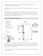
Make sure that the end of the brine tubing is cut square and that the tubing coating is
smooth, unmarred, and undamaged.
2.
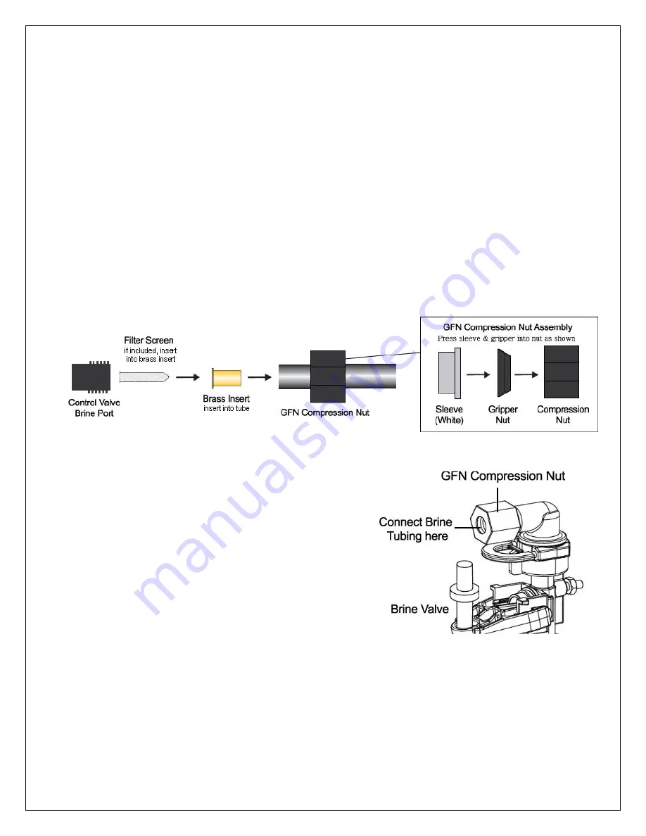
Slide the GFN compression nut onto the end of the brine tubing with the open end
facing the end of the tubing.
3.
Insert the brass tubing insert into the end of the brine tubing.
4.
Insert the filter screen into the brass insert.
5.
Center the tubing on the brass brine port on the control valve and thread the GFN
compression nut onto the brine port (clockwise). Securely tightly. Excessive forced is
not required and should not be used.
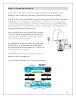
Remove the lid off the top of the brine tank.
Look inside your brine tank and you will see
a vertical white tube called the brine well.
Remove the cap from the top of the brine well.
Inside the brine well, you will find the brine valve
with air check and safety float. The other end of
the brine tubing connects to the top of the brine
valve in the same manner as the connection to
the brine port on the control valve except there
is no filter screen. There is a small hole drilled in
the brine tank and brine well that you insert the brine
tube through to connect it to the brine valve. Feed a small length of brine line through this
hole and connect it to the brine valve assembly using a brass insert and the existing plastic
GFN compression nut that is attached to the brine valve.

