10
ADH-Series | Version 1.05
Installation and erection
- The Planer-Thicknesser must only be installed and
operated in a dry, frost-free and well-ventilated
place.
- Avoid places nearby machines generating chips
or dust.
- Provide sufficient space for the staff preparing and
operating the machine and transporting the mate-
rial. Also consider that the machine is accessible
for setting and maintenance works.
- Provide for sufficient illumination (Minimum value:
300 lux)
- There must be a extraction device with min.
690 m
3
/h extraction capacity, min. 20 m/s flow rate
at the hood connection; Hose diameter 65 mm,
max. hose length 4 m.
7.2 Installation of the Planer-Thicknesser
The Planer-Thicknesser is shipped complete in one car-
ton and Is already largely assembled. After delivery only
a few parts have to be installed.
Step 1: After unpacking from the carton lift the machine
and put it at the desired place of use.
Installation on a workbench
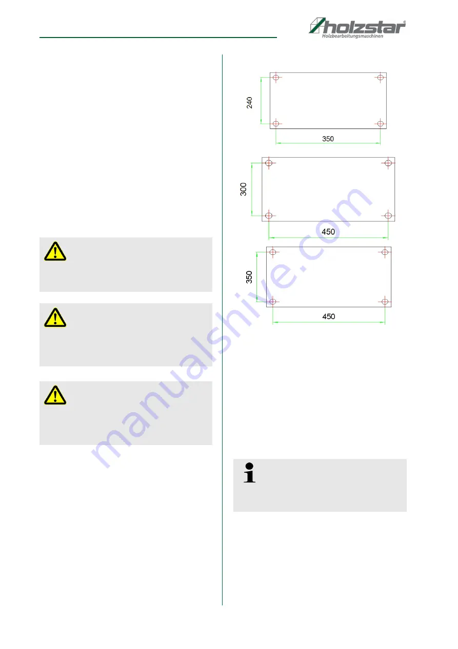
The Planer-Thicknesser can be installed on a
workbench using bolts, lock washers and hex nuts (not
supplied).- The planer-thicknesser must be bolted to a
firm, level surface.
Make sure the planer-thicknesser doesn‘t rock and the
tables are level.
Fig. 5: Hole separation ADH 200 / ADH 250 / ADH 305
Mounting of the parts
Step 1: Attach the aluminium fence on the Planer-
Thicknesser with the 6 -1.0 x 16 mm screws.
Step 2: Assembly the Chip extraction hood with the two
brackets (depending on the operating mode)
and activate the safety switch.
Step 3: Connect the extraction hose and the dust bag.
Install of the extraction hose
Step1: Connect a extraction hose diameter 65 mm with
hose clamp on the ventilation hood connection of
the machine. Connect the other end of the ext-
raction hose with a hose clamp at intake socet of
the chip extraction hood.
ATTENTION!
Risk of injury through an unstable stand of the machine!
Check the stability of the machine after installation on a
stable backgroud.
ATTENTION!
Consider the weight of the machine!
The machine may be installed only by two persons.
Check the tools corresponding to sufficient dimen-
sioning and load carrying capacity.
ATTENTION!
To ensure sufficient stability of the machine, it should
be screwed to the ground. For this purpose, 4 drill
holes are located at the bottom of the machine hou-
sing
Tips and recommendations
The extraction device must ensure a extraction
capacity from min. 690 m
3
/h by flow rate min. 20 m/s
at the hood connection.
Summary of Contents for ADH 200
Page 1: ...Instruction manual ADH S ERIES Planer Thicknesser ADH 200 ADH 250 ADH 305 ADH 250 ADH 200 ...
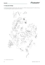
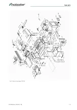
Page 19: ...Spare parts ADH Series Version 1 05 19 Fig 18 Spare parts drawing ADH 250 ...
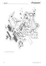
Page 20: ...20 ADH Series Version 1 05 Spare parts Fig 19 Spare parts drawing ADH 305 ...
Page 22: ...www holzstar de ...


