background image

 Page | 15


H-

RTK

Using U-Center for diagnostics


You can also use the more advanced features of the U-Center software to see how the GPS units 
are performing and working. This can be especially useful for troubleshooting. 

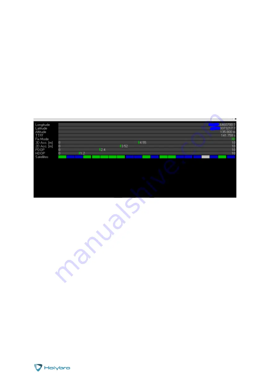
To do this, connect the base station to the U-Center software, and check whether the Fix Mode 
column is displayed as TIME in the box in the upper right corner of the software interface. 

In Fix mode the screen will display all of the statuses of your GPS unit including the position, 
accuracy and HDOP details. In the figure below, Fix Mode is displayed as 

3D Mode

, so it has not 

yet reached the RTK standard needed for more accuracy. 

There are a number of common reasons for the base station not entering TIME Mode: 

The signal received by the base station is not strong enough. 

Check the current star search signal of the base station, and view the dialog box at the bottom 
right corner of the software interface. The bar in the dialog box represents the current satellite 
received by the base station, and one bar represents a satellite (GPS or Beidou /GLONASS, 
depending on the navigation system you choose to receive). The requirements for the base 
station to enter TIME Mode are as follows: 5 GPS satellite s2 GLONASS satellite signals 
with a strength above 40; Or 5 GPS satellite s3 Beidou satellite signals above 40. In the 
figure below, if only one satellite has a strength higher than 40, the signal condition fails to meet 
the RTK standard.  

Try repositioning the GPS unit to get a clearer view of the sky. 

Summary of Contents for H-RTK F9P GNSS

Page 1: ...Page 1 H RTK H RTK M8P F9P GNSS Full Manual Installation Guide V1 2...

Page 2: ...ettings to the GPS unit on your model Updating your GPS unit 10 Downloading the software and firmware Uploading the new firmware to the GPS units Confirming the version of the newly loaded firmware Us...

Page 3: ...te your GPS units for the best possible performance Warranty and Return Policy If you believe that your HolyBro product is defective please contact us If we determine that the product is defective it...

Page 4: ...refer to the link for more information https docs px4 io en advanced_features rtk gps html Before you start Make sure you have the following pieces handy before you start this process H RTK M8P Rover...

Page 5: ...RTK M8P Rover Lite to the GPS port on your flight controller using the 10 pin connector cable Connect another telemetry radio to the TELEM1 interface of the flight controller Be aware that older Pixh...

Page 6: ...d select the RTK GPS Inject tab Check the Inject MSG Type Send GCA M8P F9P Autoconfig and M8P FW 130 F9P Select the correct base module com port in the top left corner and click connect In the SurveyI...

Page 7: ...ve the absolute accuracy of 2m about an hour to achieve the absolute accuracy of 30cm and several hours to achieve the accuracy of 10cm It should be noted that the absolute geographic accuracy of the...

Page 8: ...cation the base station will enter the fixed point mode and display the status in the box on the right When you set the base station at the same location in the future you don t need to search again j...

Page 9: ...r accuracy and only available then the signal is good enough 3D RTK is the uniform display mode of RTK Float RTK Fixed for the Chinese version of Mission Planner Refer to the latest Mission Planner do...

Page 10: ...M8P module is the firmware version of Ublox 1 40 This version of firmware supports other satellite systems Glonass Beidou and GPS fusion for RTK computing that increases the performance of RTK positio...

Page 11: ...USB cable To update the H RTK M8P Rover Lite module you need to connect the module to the USB UART small board and the small board is then connected to the computer As shown in the figure below Open...

Page 12: ...above step For the base station use DO_EXT_301_HPG_140_REFERENCE ab799cc302b64f28ba73b55dfa945a04 bin For the H RTK M8P Rover use DO_EXT_301_HPG_140_ROVER 91bbd17d889e0fe40c2d823991595224 bin In the...

Page 13: ...ul then the upgrade interface status is displayed in green Confirming the version of the newly loaded firmware Once the upload is complete you can confirm the updated version of the firmware on the mo...

Page 14: ...ed to U Center the connection mode is the same as the upgrade process above click the bug icon below to open the Debug Message Then click enter view message view ubx rxm RTCM input status and right cl...

Page 15: ...of common reasons for the base station not entering TIME Mode The signal received by the base station is not strong enough Check the current star search signal of the base station and view the dialog...

Page 16: ...the previously stored log of the Rover module Enter the Messages view nmea GxGGA directory and observe the Age of DGNSS Corr parameter parameters This parameter represents the time when the Rover mod...

Page 17: ...ck of sufficient accuracy You only need to change the Mode to Fixed Mode on the TMODE3 tab and then enter the known base station location as shown below After setting the star search and fixed point m...

Page 18: ...es view ubx CFG Configuration page and click Save Current Configuration option then click Send as shown below Note The base station and Rover module must have the same Settings and use the same naviga...

Page 19: ...ect USB in the target column The correct input and output protocols are shown in the figure below You can select the type of output you want and the protocol you want on this page In addition to these...

Page 20: ...ion output frequency you can enter the Messages view ubx cgf RATE setting and change the Measurement Period For example change the Measurement Period to 200ms and the Measurement output Frequency will...

Reviews: