Operator’s manual
Notice d’utilisation
Betriebsanleitung
monty 3850
25
Form
monty 3850
_efg - Release
Feb.2015
HOFMANN reserves the right of modification without notice
Modéle monty 3850_efg - Release Feb.2015
HOFMANN se réserve le droit d’y apporter des modifications sans préavis
Modell
monty 3850
_efg - Ausgabe
Feb.2015
HOFMANN behält sich das Recht zu Änderungen ohne Vorankündigung vor
4.
Raise the toolholder arm to the rest
position.
5.
Move the toolholder arm to the inter-
nal position.
Lower the arm and secure.
Bring the tool in contact with the in-
ner bead.
6.
Break the inner bead as described in
point #2 above.
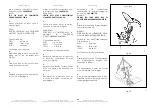
7.
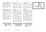
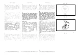
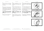
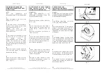
Continue rotating the chuck, moving
the tool-holder carriage towards until
the beads are demounted from the
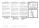
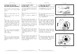
rim (Fig.19).
IMPORTANT!
IF USING THE TUBELESS ROLLER
BLOCK THE ARM ONLY IN POSITION
3 (Fig. 5.5a).
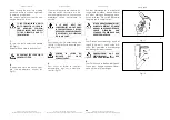
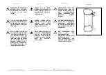
ENSURE THAT THE OUTER BEAD
SLIDES
INTO
THE
DROP
CENTER OPPOSITE TO THE
TOOL,
OTHERWISE
THE
DEMOUNTING OPERATION IS
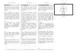
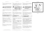
IMPOSSIBLE (Fig.20).
8.
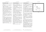
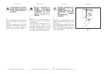
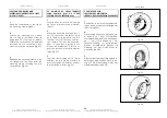
Move to the front of the tire and hold
it with both hands in the last part of
demounting operation to prevent the
tire from falling or rolling away out of
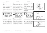
control (Fig.21).
4.
Soulever le bras porte-outil en posi-
tion de repos.
5.
Faire coulisser le bras porte-outil dans
la position intérieure.
Abaisser le bras et le bloquer.
Placer l’outil en contact avec le ta-
lon intérieur.
6.
Détalonner le talon intérieur comme
décrit au point #2.
7.
Continuer à tourner l’arbre en dé-
plaçant le cariot porte-outil vers
l’intérieur jusqu’à faire sortir les deux
talons de la jante (Fig.19).
IMPORTANT!
DANS LE CAS D'UN ROULEAU
TUBELESS, BLOQUER LE BRAS
EXLUSIVEMENT DANS LA POSITION
3 (Fig. 5.5a).
VÉRIFIER
QUE
LE
TALON
EXTÉRIEUR DESCENDE DANS LE
CANAL DE LA JANTE EN
POSITION
DIAMÉTRALEMENT
OPPOSÉE À L’OUTIL. DANS LE CAS
CONTRAIRE, LE DÉMONTAGE EST
IMPOSSIBLE (Fig.20).
8.
Se placer face au pneu et le retenir
des deux mains dans la phase finale
du démontage pour éviter qu’il ne
tombe ou ne roule de façon incon-
trôlée (Fig.21)
4.
Den Werkzeugarm in Ruhestellung
aufrichten.
5.
Den Werkzeugarm in die Innenpositi-
on gleiten lassen. Den Arm nach un-
ten stellen und arretieren. Das Werk-
zeug an die innere Wulst anlegen.
6.
Die innere Wulst wie unter Punkt #2
beschrieben abdrücken.
7.
Das Spannfutter weiterdrehen und
dabei den Schlitten soweit nach au-
ßen fahren, bis die beiden Wülste aus
der Felge herauskommen (Abb.19).
WICHTIG!
FALLS DIE TUBELESS-ROLLE
VERWENDET WIRD, DARF DER ARM
AUSSCHLIESSLICH IN DER POSITION
3 FESTGESTELLT WERDEN (Abb.
5.5a).
SICHERSTELLEN,
DASS
DER
ÄUSSERE
WULST
GENAU
GEGENÜBER VOM WERKZEUG
INS
TIEFBETT
RUTSCHT,
ANDERN-FALLS
KANN
DIE
DEMONTAGE
NICHT
ERFOLGREICH
DURCH-
GEFÜHRT WERDEN (Abb.20).
8.
Sich gegenüber vom Reifen aufstellen
und diesen in der Endphase der De-
montage mit beiden Händen festhal-
ten um zu verhindern, daß der Reifen
herunterfällt oder unkontrolliert weg-
rollt (Abb.21).
580
Fig.19
581
Fig.19a
410
411
Fig.20
Fig.21

