background image

EN

10

®

T-28 Trojan S 

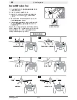
Control Direction Test

Up Elevator (climb)

Down Elevator (descend)

Rudder Left

Rudder Right

1.  Place the aircraft into 

Experienced mode

 (Mode 

switch position 2).

2.  Face the aircraft away from you. 
3.  Restrain the aircraft so it does not escape your 

control while you are testing your transmitter 

controls.

4.  Move the sticks on the transmitter to ensure the 

aircraft responds as shown. 

5.  If the aircraft responds as shown, move the SAFE

®


mode switch to 

Beginner mode

 (Position 0) to 

prepare to fl y. 

Refer to the Binding instructions and Troubleshooting 

Guide in this manual for more information. If you need 
more assistance, contact the appropriate Horizon 
Hobby Product Support department. 

Mode 2 shown

Aileron Left

Aileron Right

Experienced Mode
(Switch Position 2)

erienced Mod

1

2

0

Summary of Contents for UM T-28 Trojan S

Page 1: ...Instruction Manual Bedienungsanleitung Manuel d utilisation Manuale di Istruzioni UM T 28 Trojan S RESCUE ...

Page 2: ...AUTION Procedures which if not properly followed create the probability of physical property damage AND a possibility of serious injury WARNING Procedures which if not properly followed create the probability of property damage collateral damage and serious injury OR create a high probability of superficial injury Safety Precautions and Warnings Always keep a safe distance in all directions around ...

Page 3: ... View FPV 16 Troubleshooting Guide 17 Re Binding the RTF Transmitter 17 Limited Warranty 19 Warranty and Service Contact Information 20 FCC Information 20 IC Information 20 Compliance Information for the European Union 20 Replacement Parts 81 Optional Parts 82 Table Of Contents Components RTF BNF Basic Motor 8 5mm Brushed Motor in Gearbox EFLRMLP6 Installed Installed Receiver SAFE Receiver and ESC...

Page 4: ...nsmitter Batteries Installation Throttle Rudder Power LED Battery Door Power Switch Elevator Trim Down Aileron Elevator Aileron Trim Right Elevator Trim Up Aileron Trim Left Throttle Trim Down Rudder Trim left Throttle Trim Up Rudder Trim Right Flight Mode Switch Bind Panic Recovery Trigger Bind Button Ail Dual Rate Button Mode 2 shown DXe Transmitter Setup To use a Spektrum DXe transmitter downlo...

Page 5: ... DX7S DX8 DX7 G2 DX8 G2 DX9 DX18 and DX20 Start all transmitter programming with a blank model do a model reset then name the model Set Dual Rates to HIGH 100 LOW 70 DX6i 1 Go to the SETUP LIST MENU 2 Set MODELTYPE ACRO 3 Set REVERSE Gear Channel 4 Go to ADJUST LIST MENU 5 Set TRAVEL ADJ Gear Fmode 0 100 Gear Fmode 1 40 6 Set FLAPS Norm 100 LAND 100 7 Set MIX 1 ACT Gear Gear ACT RATE D 0 U 100 SW ...

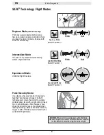
Page 6: ... return the aircraft to a stable attitude wings level with a slight climb Always fly at a safe altitude as Panic Recovery may cause the aircraft to lose some altitude when leveling the wings Release the Panic Recovery trigger to turn off Panic mode and return to the current SAFE fight mode Roll Pitch Roll Pitch Roll Pitch Beginner Mode Switch Position 0 Intermediate Mode Switch Position 1 Experience...

Page 7: ... the main landing gear assemblies into the plastic brackets on the bottom of the wing with the struts toward the front of the wing Installing Landing Gear 2 Ensure the landing gear wires are fully inserted into the clip so the end of the wire snaps into place 3 Insert the nose gear into the plastic nose gear mount on the bottom of the fuselage ...

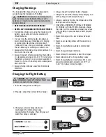
Page 8: ... of the battery pack while charging ONLY USE A CHARGER SPECIFICALLY DESIGNED TO CHARGE LI PO BATTERIES Failure to charge the battery with a compatible charger may cause a fire resulting in personal injury and or property damage Never discharge Li Po cells to below 3V under load Never cover warning labels with hook and loop strips Never charge batteries outside recommended levels Never charge damage...

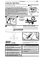
Page 9: ...ransmitter s unique instructions for binding to a receiver 2 Make sure the flight battery is disconnected from the aircraft 3 Ensure the transmitter is powered OFF 4 Connect the flight battery to the aircraft and turn the aircraft upright The receiver LED will begin to flash typically after 5 seconds 5 Make sure the transmitter controls are at neutral and the throttle is in the low position 6 Put you...

Page 10: ...our transmitter controls 4 Move the sticks on the transmitter to ensure the aircraft responds as shown 5 If the aircraft responds as shown move the SAFE mode switch to Beginner mode Position 0 to prepare to fly Refer to the Binding instructions and Troubleshooting Guide in this manual for more information If you need more assistance contact the appropriate Horizon Hobby Product Support department M...

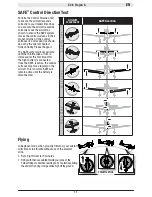
Page 11: ...rottle stick or trim is increased for the first time after the flight battery is connected Once the SAFE is active the control surfaces may move rapidly on the aircraft This is normal SAFE will remain active until the battery is disconnected Aircraft movement SAFE Reaction E l e v a t o r A i l e r o n R u d d e r Flying In Beginner mode when properly trimmed your aircraft will climb at full throttl...

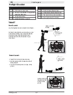
Page 12: ...Gently pull back on the elevator stick to lift off of the ground n 9 1 Find a safe and open area 2 Set up your transmitter to support SAFE technology BNF only 3 Charge flight battery 4 Install flight battery in aircraft 9 5 Perform Control Direction Test 6 Perform SAFE Control Direction Test 5 Plan flight for flying field conditions 6 Set a flight timer for 5 minutes Preflight Checklist Ground Launch Tak...

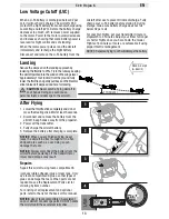
Page 13: ...o LVC will damage the battery Low Voltage Cutoff LVC After Flying 1 Lower the throttle stick completely and do not move the steering stick Wait at least 5 seconds 2 Disconnect and remove the battery from the aircraft Keep hands away from the propeller 3 Power off the transmitter 4 Fully charge the aircraft battery 5 Remove the battery after charging is complete NOTICE When you are finished flying ne...

Page 14: ... left drift Left button to stop right roll Right button to stop left roll If you press a trim button until no beep sounds and the aircraft does not fly straight and level land and manually adjust the trim as described below Manually Adjusting Trim Press the trim buttons to return to center 3 beeps will sound then use a pair of pliers to carefully bend the metal U Bend Only adjust elevator to neutra...

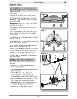
Page 15: ... the shaft clockwise facing the front of the model to remove the nut 8 Gently pull the shaft B from the gearbox C and make sure the washer D and two bushings E are not lost 9 Disconnect the motor from the ESC receiver 10 Gently push the motor out of the gearbox and remove the motor NOTICE DO NOT remove the gearbox from the aircraft Damage to the aircraft will result Assembly Assemble the aircraft ...

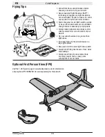
Page 16: ...ilot The pilot is always in control and required to fly the aircraft at all times Start in Beginner mode SAFE switch position 0 As you learn and become more confident change modes to advance your flying skills Always make deliberate and steady control stick movements for smooth control of your aircraft Fly your aircraft outside in no greater than light winds For indoor flight fly the aircraft inside in...

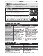
Page 17: ...ver is bound to the transmitter If the LED does not turn solid refer to the Troubleshooting Guide at the end of the manual 7 Disconnect the flight battery and power the transmitter off Re Binding the RTF Transmitter The transmitter included in the RTF package comes pre bound to the aircraft To re bind the aircraft follow this binding table Problem Possible Cause Solution Control surfaces not at neu...

Page 18: ...delMatchTM radios only Select correct model memory on transmitter and disconnect and reconnect flight battery to aircraft Flight battery transmitter battery charge is too low Replace recharge batteries Transmitter may have been bound to a different model or with a different DSM Protocol Select the right transmitter or bind to the new one Aircraft or transmitter is too close to large metal object wi...

Page 19: ...nd service you in the event that you may need any assistance For ques tions or assistance please visit our website at www horizonhobby com submit a Product Support Inquiry or call the toll free telephone number referenced in the Warranty and Service Contact Information section to speak with a Product Support representative Inspection or Services If this Product needs to be inspected or serviced an...

Page 20: ...lies with part 15 of the FCC rules Operation is subject to the following two conditions 1 This device may not cause harmful interference and 2 this device must accept any interference received including interference that may cause undesired operation NOTICE Modifications to this product will void the user s authority to operate this equipment FCC Information IC Information IC 6175A BRWDXMT and 6157...

Page 21: ...rojan S Aile peinte UM T 28 Trojan S Ala verniciata UM T 28 Trojan S HBZ5603 Painted Tail set UM T 28 Trojan S Höhenleitwerk Satz lackiert UM T 28 Trojan S Empennage peint UM T 28 Trojan S Set coda verniciata UM T 28 Trojan S HBZ5604 Decal Set UM T 28 Trojan S Decal Satz UM T 28 Trojan S Lot d autocollants UM T 28 Trojan S Set decalcomanie UM T 28 Trojan S HBZ5605 Landing Gear set UM T 28 Trojan S...

Page 22: ...adegerät Chargeur de batterie CA CC Ultra Micro 4 4 x 9 W Caricabatteria AC DC Ultra Micro 4 4X9 W PKZ1039 Hook Loop Set 5 Ultra Micros Set Haken und Schlau fe 5 Ultra Mikros Set de bandes auto agrippantes 5 Ultra Micros Set fascette a strappo 5 Ultra Micros SPMVA1100 Spektrum Ultra Micro Camera and VTX Spektrum Ultra Mikro kamera und VTX Caméra et VTX Spektrum Ultra Micro Videocamera e trasmet ti...

Page 23: ...tch Focal and the Horizon Hobby logo are trademarks or registered trademarks of Horizon Hobby LLC The Spektrum trademark is used with permission of Bachmann Industries Inc US 9 056 667 US 8 672 726 US 7 898 130 US D578 146 PRC ZL 200720069025 PRC ZL 2007001249 www hobbyzonerc com Created 05 2017 55553 HBZ5600 HBZ5650 ...

Reviews: