11
❏
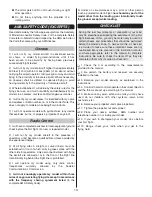
6. When checking the propeller operation,
BE SURE
TO KEEP YOUR HANDS, CLOTHING, ETC. BEHIND
THE SPINNING ARC OF THE PROPELLER!
Operate the
propeller outside, clear of any obstacles, and be sure that
you have a fi rm grasp on the airplane before applying throttle.
OPERATING THE ESC
NECESSARY TRANSMITTER SETTINGS
If you are using a transmitter other than a Tactic transmitter,
it’s very important to set the transmitter’s throttle channel
adjustments, as follows:
1. Set the throttle channel’s travel adjustment (ATV,EPA or
ATL) to 100%.
2. Set the throttle trim and sub-trim to neutral or zero.
3. Set the throttle channel’s reversing switch to reverse on
Futaba
®
transmitters. Other transmitters might require you
to set the throttle reversing switch to normal.
LOW VOLTAGE CUT-OFF
The Mini Switch ESC includes a low-voltage cut-off feature
that stops motor rotation if the battery’s voltage drops too low.
This protects the battery from damage due to under-voltage
conditions. When the low voltage cut-off stops motor rotation
it will still supply power to the receiver and all control surfaces
except throttle, so you can maintain control of the aircraft.
NORMAL STARTUP PROCEDURE
1. Unless calibrating the throttle or programming the ESC,
always turn on the transmitter with the throttle stick all the
way down. Turn on the transmitter.
2. Connect the battery to the ESC. Listen for the three
tones…“ 1 2 3 ” followed by three short beeps…“beep
beep” beep” followed by one long beep…“beeep”.
Now the ESC is “armed” and the model is ready to fl y. The
propeller will turn whenever the throttle stick is advanced,
so use caution. When you are done running the motor or
fl ying the plane simply disconnect the battery and turn off
the transmitter.
Check the Control Throws
The Mini Switch is setup from the factory with the
recommended control throws for the high wing
configuration. If at any time you wish to return to
the default control throws, or if you simply want to
confirm the throws, use the following measurements:
NOTE
: The throws are measured at the
widest part
of the
elevators, rudder and ailerons.
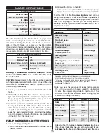
These are the recommended control surface throws:
ELEVATOR
Up & Down
5/16"
[8mm]
16 deg
RUDDER
Right & Left
1/4"
[6mm]
8 deg
AILERONS
Up & Down
5/16"
[8mm]
12 deg
ELEVATOR
Up & Down
5/16"
[8mm]
16 deg
RUDDER
Right & Left
3/8"
[9.5mm]
12 deg
AILERONS
Up & Down
HIGH
WING
CONFIGURA
TION
LO
W
WING
CONFIGURA
TION
5/16"
[8 mm]
12 deg
Check the Balance (C.G.)
More than any other factor, the C.G. (center of gravity/
balance point) can have the greatest effect on how a
model fl ies and could determine whether or not your fi rst
fl ight will be successful. If you value your model and wish
to enjoy it for many fl ights,
DO NOT OVERLOOK THIS
IMPORTANT PROCEDURE.
A model that is not properly
balanced may be unstable and possibly unfl yable.
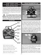
With the battery installed along with the propeller, spinner and
hatch, the Mini Switch is designed to balance at the position
shown without you needing to add any additional ballast to
the nose or tail.
❏
1. For the high wing version, apply narrow (1/16" [2mm])
strips of tape 2" [51mm] from the leading edge of each wing
panel onto the underside of the wings as shown (you can
also apply some masking tape and draw the lines with a
felt-tip pen). If you are balancing the plane in the low wing
confi guration, apply the strips of tape 2-11/16" [68mm] fron
the wing’s leading edge on the top of the wings.


