


14
ENGLISH
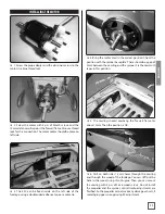
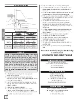
SET THE CONTROL THROWS
These are the recommended
control surface throws :
Elevator
3D rate
Normal aerobatics
Maximum
Up
Maximum
Down
20 mm
Up
20 mm
Down
Rudder
Maximum
Right
Maximum
Left
40 mm
Right
40 mm
Left
Ailerons
Maximum
Up
Maximum
Down
30 mm
Up
30 mm
Down
CHECK-LIST
During the last few moments of preparation your mind
may be elsewhere anticipating the excitement of the
first flight. Because of this, you may be more likely to
overlook certain checks and procedures that should be
performed before the model is flown. To help avoid this,
a checklist is provided to make sure these important
areas are no overlooked. Many are covered in the
instruction manual, so where appropriate, refer to the
manual for complete instructions. Be sure to check the
items off as they are completed (that's why it's called a
check list!).
❍
1. Check the C.G. according to the measurements
provided in the manual.
❍
2. Be certain the battery and receiver are securely
mounted in the fuse. Simply stuffing them into place with
foam rubber is not sufficient.
❍
3. Look for a correct position of your receiver antenna or
antennas. The antenna should not be close to other wires
inside the fuselage.
❍
4. Balance your model also laterally.
❍
5. Use threadlocking compound to secure critical
fasteners such as the set screws that hold the wheel
axles to the struts, screws that hold the carburetor arm (if
applicable), screw-lock push rod connectors, etc.
❍
6. Make sure all hinges are securely glued in place.
❍
7. Reinforce holes for wood screws with thin CA where
appropriate (servo mounting screws, cowl mounting
screws, etc.).
❍
8. Confirm that all controls operate in the correct direction
and the throws are set up according to the manual.
❍
9. Make sure there are silicone retainers on all the clevises
and that all servo arms are secured to the servos with the
screws included with your radio.
❍
10. Secure connections between servo wires and Y
connectors or servo extensions and the connection
between your battery pack and the on/off switch with
vinyl tape, heat shrink tubing or special clips suitable for
that purpose.
❍
11. Make sure any servo extension cords you may have
used do not interfere with other systems (servo arms,
push rods, etc.).
❍
12. Balance your propeller (and spare propellers).
❍
13. Tighten the propeller nut and spinner.
❍
14. Place your name, address, AMA number and
telephone number on or inside your model.
❍
15. Inspect all cables from flight to flight!
❍
16. If you wish to photograph your model, do so before
your first flight.
❍
17. Range check your radio when you get to the flying
field.
Have a ball! But always stay in control and fly
in a safe manner.
GOOD LUCK AND GREAT FLYING!
HOBBICO SERVICE LINE EUROPE
Service department Revell GmbH
Henschelstr. 20-30, 32257 Bünde, Germany
Tel: +49 52239 65144
Email: [email protected]
HOBBICO SERVICE LINE USA
Hobbico Product Support
3002 N. Apollo Drive Suite 1
Champaign IL 61822 USA
Telephone: (217) 398-8970 ext. 6
Fax: (217) 398-7721
E-mail: [email protected]
FLITEWORK SERVICE LINE
Service department Flitework GmbH
Geymannstr. 27, 4713 Gallspach, Austria
Tel: +43 664 3231 059
Email: [email protected]
Summary of Contents for Edge 540 RB FLWA4140
Page 15: ...15 ENGLISH NOTES...


