8
MM06UE01-2002
3.3 Functional description
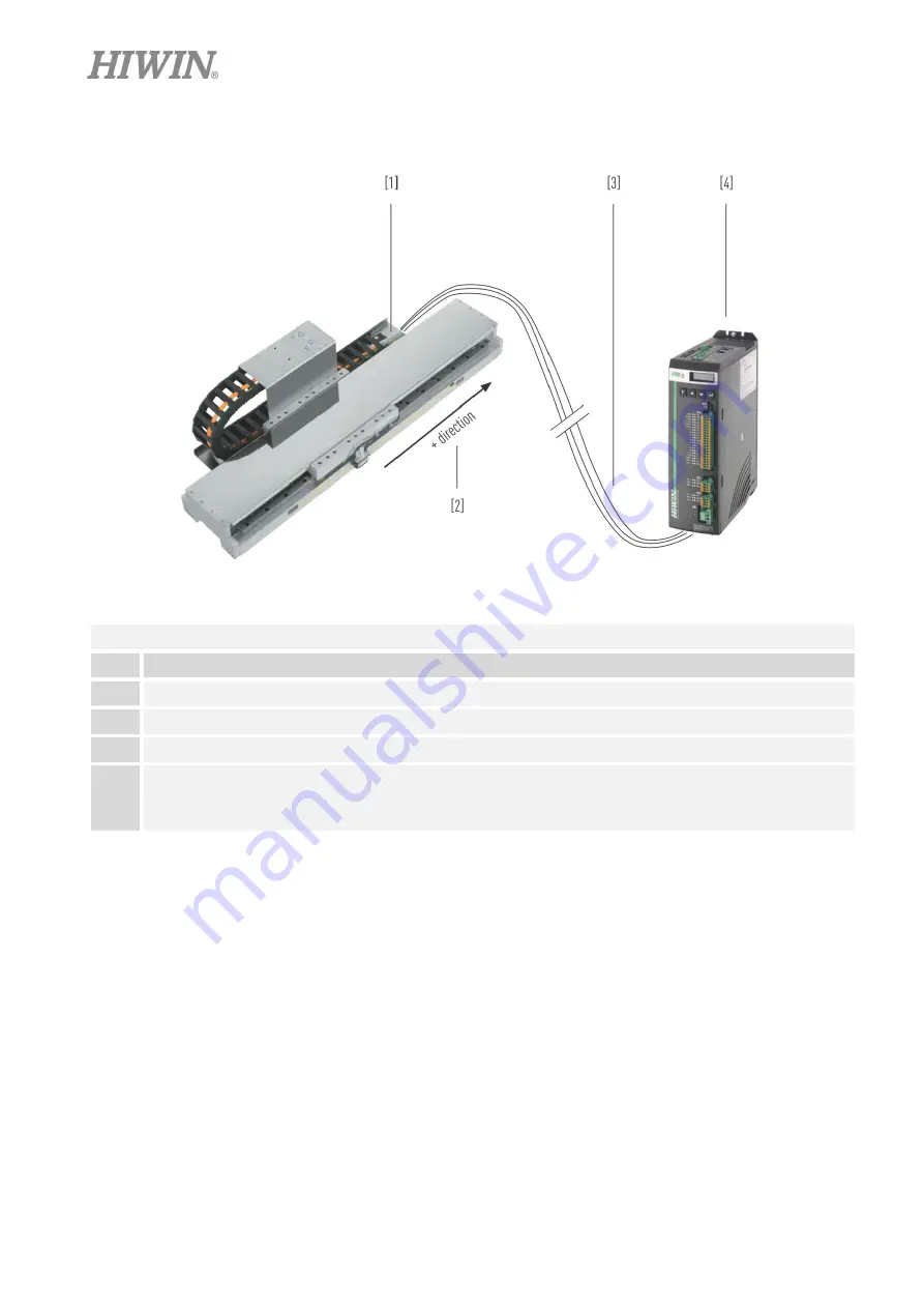
Fig. 3.2
Principle of the
linear motor system
Table 3.2
Components and functionality
Pos. Function
1
Energy supply (standard version or customer-specific version)
2
Positive (+) direction of motion. This is defined via the position of the reference switch.
3
Motor cables, positioning measurement system, limit switches.
4
●
Drive D1
●
Drive D1-N (with functional safety, suggested for users from Europe)
●
Drive D2T-LM
3.3.1 Linear motor system
A linear motor system comprises a base with integrated linear guideways These both absorb the forces exerted by
the weights, accelerations, and processes and provide precise guiding for the forcer housing. The axis is driven by
linear motors.
3.3.2 Linear motor
A linear motor consists of two components, the forcer (primary part) with coils and the stator (secondary part) with
permanent magnets. The coils carrying alternating current generate a magnetic field that changes over time and
interacts with the steady magnetic field of the stator. The resulting force is used to generate linear motion. The linear
motor components are supplied as separate parts.


