background image


05.17 207646 Rev.103


EKWXA│EKWXBA


AIR-COOLED WATER CHILLERS 

AXIAL FANS 

DESCRIPTION OF THE UNIT 

 
The EKWXA / EKWXBA units are compact reversible WATER / AIR units for the production of hot / cold water. They are designed  for 
outdoor installation. Supplied with R-410A refrigerant charge, ready for installation.  
 
These units are manufactured under a strict quality control throughout their process and once finished are tested in the factory, verifying 
the correct operation of all its components. 
 
The unit is composed by: 


Hermetic compressor, alternative, with wide operating limits. It incorporates thermal protection of the windings (without requiring 
additional protection), the oil load for its perfect lubrication and internal damping system. The compressor is mounted on the chassis 
with shock absorbers and is acoustically insulated. All this guarantees a silent operation and without vibration. 


External coils built with copper tube without welds and expanded in aluminum fins. Incorporate distributor with neck and calibrated 
orifice (nozzle) to improve distribution of the gas in Cold mode. 


Coolant-water exchanger made from stainless steel plates (AISI 316) welded with bronze base. It is perfectly insulated with insulating 
heat material to prevent the exchange of heat with the outside. It has built-in electrical heaters as an anti-ice protection to avoid the 
risks of breaking it by freezing the water in case of lack of flow. 


Fan motor mounted with a square base and circular inlet embouchure suitable for the aerodynamic performance of the flow driven 
by the fan itself. Ready for outdoor installation, totally closed, with permanent lubrication. It consists of aluminum blades designed 
to  obtain  a  low  sound  level,  inserted  into  the  outer  rotor  of  a  high  efficiency  motor,  with  IP-54  protection  and  class  F  winding 
insulation. It has internal thermal probes incorporated for its protection, as well as external security grid.  


Thermostatic expansion valve with MOP at the plate exchanger inlet for cooling mode operation. The expansion in the external coil, 
when necessary (operation in heating mode), is realized through a hole. 


Safety pressure switch connected to the compressor output (maximum pressure point) of manual reset. Its cut is  calibrated at a 
pressure of 42 bars. 


Bidirectional dehydrator filter type mounted on the liquid line. It consists of a solid desiccant core that minimizes vibration and friction 
during the operation of the equipment besides absorbing excess moisture and filter any impurities. 


Tank to contain the variations of the refrigerant charge required by the machine when changing its operation between Cool/Heat. 


Check valves only on Heat Pump units to bypass the expansion system of the secondary exchanger block. Cold mode performs the 
bypass to battery, in Heat mode, it is done to the expansion valve. 


The sheet metal structure of these equipments is resistant to the weather and is formed by galvanized steel sheet which is applied 
an oven painting process by polymerization of powder paint which provides excellent overall coating and especially in corners and 
edges. The self-supporting base is constructed with highly rigid steel. The rest of the structure is galvanized steel. The design is 
done for an easy maintenance. The finished set has RAL 1013 color. 


Summary of Contents for EKWXA 7002.4

Page 1: ...enance Manual 05 17 207646 Rev 103 EKWXA EKWXBA AIR COOLED WATER CHILLERS AXIAL FANS Models 7002 4 8002 4 9002 4 Cooling Capacities from 178 3 kW to 213 6 kW Heating Capacities from 194 9 kW to 244 2...

Page 2: ...efficiency adaptability usability and practical solutions This has been the hallmark of our product catalogue The versatility of our factory allows us to contribute solutions almost tailored to each p...

Page 3: ...IBUTION 13 Model 7002 4 13 Models 8002 4 9002 4 13 INSTALLATION LOCATION 14 UNIT SETTLEMENT 14 WATER DRAIN 14 ELECTRICAL CONNECTIONS 14 SERVICE AREA 15 Model 7002 4 15 Models 8002 4 9002 4 15 OPERATIO...

Page 4: ...dels 8002 4 9002 4 21 System Parameters 22 Regulation Parameters 23 Compressors 23 Alarms 24 HYDRONIC KIT 26 TECHNICAL DATA 26 OPERATING LIMITS 27 MAINTENANCE 27 CONSERVATION AND CLEANING 27 LUBRICANT...

Page 5: ...built in a way that does not pose a risk to the health and safety of people Appropriate project solutions have been adopted to eliminate the possible causes of risk in the installation Packaging and...

Page 6: ...be dangerous because the system is under pressure because some of its elements have high temperatures and include electrical components Do not install the unit in explosive atmosphere ATTENTION Only...

Page 7: ...low driven by the fan itself Ready for outdoor installation totally closed with permanent lubrication It consists of aluminum blades designed to obtain a low sound level inserted into the outer rotor...

Page 8: ...23 5 2 x 24 COMPRESSOR Type SCROLL Number of compressors 4 Number of power stages 4 Maximum current for operating circuit A 71 80 89 Locked rotor current A 249 264 309 Oil type POE 160 SZ Oil volume L...

Page 9: ...62 1 416 3 SOUND LEVEL Sound power dB A 92 8 94 7 94 8 Sound pressure 5m 5 dB A 71 72 9 73 WEIGHT AND DIMENSIONS Large mm 3200 Width mm 2250 High mm 2150 Net weight of heat pump units EKWXBA kg 1720 1...

Page 10: ...nd stable bear in mind that the heaviest part is where the compressor is installed Always transport the unit in its original packaging to the place of installation Lifting through crane STORAGE If the...

Page 11: ...COOLED WATER CHILLERS AXIAL FANS INSTALLATION DIMENSIONS Model 7002 4 1 Water inler 3 2 Water outlet 3 3 Electrical panel 4 Main switch 5 Electrical connection input 6 Optional electrical connection...

Page 12: ...LED WATER CHILLERS AXIAL FANS INSTALLATION DIMENSIONS Models 8002 4 9002 4 1 Water inler 3 2 Water outlet 3 3 Electrical panel 4 Main switch 5 Electrical connection input 6 Optional electrical connect...

Page 13: ...ing pump 233 246 194 181 185 187 248 246 1720 Cooling only 234 247 181 173 176 184 244 247 1686 Models 8002 4 9002 4 WEIGHT DISTRIBUTION kg R1 R2 R3 R4 R5 R6 R7 R8 TOTAL 8002 4 Heating pump 229 241 20...

Page 14: ...r larger than unit drain connection depending on the line length and general building configuration The condensate line should be pitched a minimum 2 for proper water evacuation When drain line is exp...

Page 15: ...15 05 17 207646 Rev 103 EKWXA EKWXBA AIR COOLED WATER CHILLERS AXIAL FANS INSTALLATION SERVICE AREA Be sure to respect the measures for a proper operation of the unit Model 7002 4 Models 8002 4 9002 4...

Page 16: ...n 7002 4 5002 4 9002 4 Bomba de Calor 7002 4 5002 4 9002 4 EKWXA EKWXBA 60 25 30 35 40 45 50 55 15 10 5 0 5 10 15 LWT C Temperatura exterior Outdoor temperature T mperature x 7 10 5 0 5 10 15 20 25 2...

Page 17: ...ain Functions of the Control System Regulates water temperature Service hour counter for compressors and water pumps optional Intake and outlet water temperature reading displays as well as pressure r...

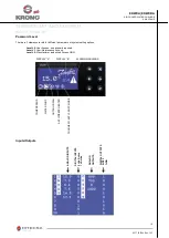
Page 18: ...t must be started up once again ESC Pressing this key leads to a shortcut to the ALARMS menu RETURN This key takes the user to the MAIN MENU screen if it is pressed in the START MENU screen It is also...

Page 19: ...meters or system setting options Level L0 User Access no password required Level L1 User Maintenance Access Level L2 Manufacturer authorized Access ONLY Inputs Outputs DISPLAY A DISPLAY B ALARMS WARNI...

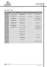
Page 20: ...e circuit 1 only heat pump 4 Cond evap pressure Cool Heat circuit 1 Thermal outdoor fans circuit 1 Antifreeze resistance circuit 1 5 Evap cond pressure Cool Heat circuit 1 Safety high pressure switch...

Page 21: ...ays valve circuit 1 only heat pump 4 Evap cond pressure Cool Heat circuit 1 Thermal outdoor fans circuit 1 Antifreeze resistance circuit 1 5 Cond evap pressure Cool Heat circuit 2 Safety high pressure...

Page 22: ...s indicates the operational mode for restart System HEAT COOL Indicates current operating mode HEAT COOL and it also allows switching between modes If the unit is running it stops before switching ope...

Page 23: ...ling more By default this value is 6 0 C High Limit Set point Temperature This is used to set the highest limit of the Set point temperature in cooling more By default this value is 17 0 C Heating Set...

Page 24: ...ressor 2 exceeded Notification A63 Service Hours For Compressor 3 Exceeded Notification A64 Service Hours For Compressor 4 Exceeded Notification A7A Intake water probe Automatic OFF OFF OFF OFF A7B Ou...

Page 25: ...ater pump 1 Automatic OFF AP2 Thermal protection water pump 2 Automatic OFF AP9 Operation reserved pump Notification E10 EEV Connection Alarm Circuit 1 Manual OFF C1 E12 EEV Reheat Temperature Alarm C...

Page 26: ...Hz 400 3 50 Number of Heat Pump 2 Reserve Heat Pump Option SI Maximum weight Heat Pump H K full of water kg 2245 2278 2284 LOW PRESSURE PUMP Model CEA 370 2 Rated Power per unit kW 1 5 Maximum Curren...

Page 27: ...al circuit Make sure that all electrical connections wires contactors and terminals are properly tight Record the readings for volts and amperes of each compressor and fan motor Verify the starting cu...

Page 28: ...h higher available pressure With this accessory is included the control of condensation of the equipment SOFT STARTER Soft starter to minimize peak currents at the compressor start ELECTRONIC EXPANSIO...

Page 29: ...cur An individual exposed to high concentrations of R410A must be given medical attention immediately Adequate ventilation must be provided at all times Recommendations Semiotics or support therapy is...

Page 30: ...emperature below 52 C Protective Clothing Wear overalls protective gloves and goggles or a mask Accidental Release Measures IIt is important to wear protective clothing and a respirator Stop the sourc...

Page 31: ...31 05 17 207646 Rev 103 EKWXA EKWXBA AIR COOLED WATER CHILLERS AXIAL FANS We reserve the right to add modifications without prior notice...

Reviews: