


--- 30 ---
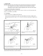
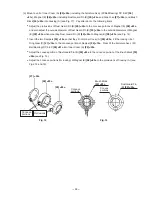
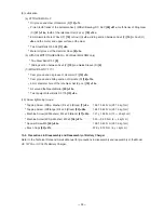
Fig. 16
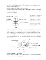
Align the protrusions of housing (A) to the concave
portions (for locking) of Magnet (E)
[28] <23>
Housing (A)
(e) Mount the DC-Speed Control Switch
[37] <32>
to housing (A) so that the protrusion of the forward/reverse
lever at the top of the switch is inserted into the hole of Pushing Button (A)
[38] <33>
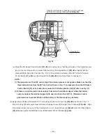
. Apply silicone
grease (KS609, Shin-Etsu Chemical Co., Ltd.) to the contacting surfaces of the FET of the DC-Speed
Control Switch
[37] <32>
and Dust Guard Fin (B)
[29] <24>
then mount them to housing (A).
NOTE:
(1) The temperature of the FET can be high if the silicone grease is not applied. Make sure that the
three internal wires from the FET are bent as shown in Fig. 17 and passed above the DC-Speed
Control Switch [37] <32> to keep from contact with Pushing Button (A) [38] <33> (see Fig. 17).
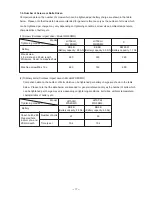
(2) If there is no plating and a black oxide is formed on the terminal support where the battery
contacts, replace the terminal support with new one (Code No. 323710). Otherwise, heat is
generated due to contact failure and the battery or the main body may be faulty.
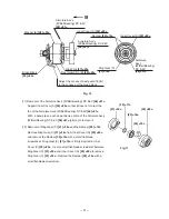
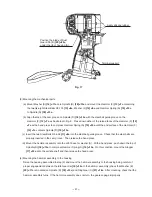
(2) Apply silicone rubber (ThreeBond 1211) to housing (A) and Inner Cover (A)
[25] <20>
as shown in Fig. 17.
Mount housing (B) and secure them with seven Tapping Screws (W/Flange) D4 x 20 (Black)
[33] <28>
. Wipe
the silicone rubber coming out of the housing with a cloth. Insert Sleeve (A)
[46] <41>
into the Strap (Black)
[45] <40>
and tighten the Machine Screw (W/Washers) M4 x 25 (Black)
[47] <42>
.