

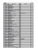
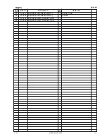
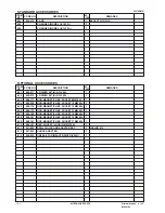
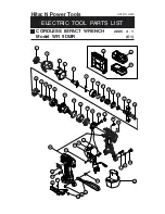
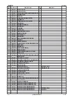
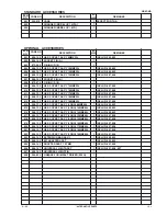


--- 29 ---
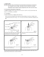
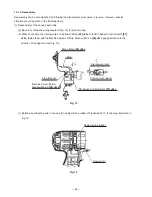
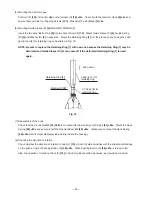
(d) Mount a unit of Inner Cover (A)
[25] <20>
(including the Armature Ass'y (W/Ball Bearing) DC 9.6V
[26]
<21>
), Magnet (E)
[28] <23>
(including Dust Guard Fin (B)
[29] <24>
and Side Yoke
[27] <22>
) and Brush
Block
[30] <25>
into housing (A) (see Fig. 17). Pay attention to the following items.
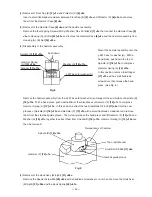
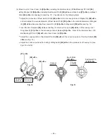
Adjust the protrusions of Dust Guard Fin (B)
[29] <24>
to the concave portions of Magnet (E)
[28] <23>
and also adjust the outside diameter of Dust Guard Fin (B)
[29] <24>
to the outside diameters of Magnet
(E)
[28] <23>
when mounting Dust Guard Fin (B)
[29] <24>
to Magnet (E)
[28] <23>
(see Fig. 14).
Insert the two Dampers
[24]
<19>
so that they fit into Inner Cover (A)
[25] <20>
. Fit the locking rib of
Ring Gear (C)
[21] <16>
to the concave portion of Damper
[24] <19>
. Press-fit the Armature Ass'y (W/
Ball Bearing) DC 9.6V
[26] <21>
into Inner Cover (A)
[25] <20>
.
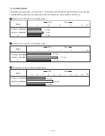
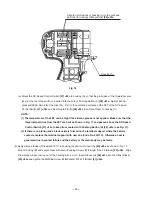
Adjust the convex portion of Dust Guard Fin (B)
[29] <24>
to the concave portion of the Brush Block
[30]
<25>
(see Fig. 15).
Adjust the concave portions (for locking) of Magnet (E)
[28] <23>
to the protrusions of housing (A) (see
Figs. 14 and 16).
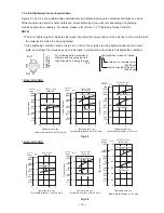
[27] <22>
[28] <23>
[29] <24>
Protrusions
Concave
portions
Brush Block
[30] <25>
Dust Guard Fin
(B)
[29] <24>
Fig. 14
Fig. 15
Concave
portions
Convex
portions