2
.
TROUBLESHOOTING
20
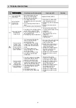
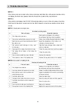
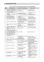
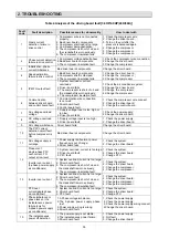
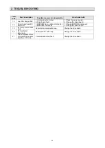
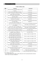
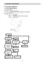
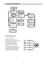
(2) Fault codes indicated by LED lamps on display panel
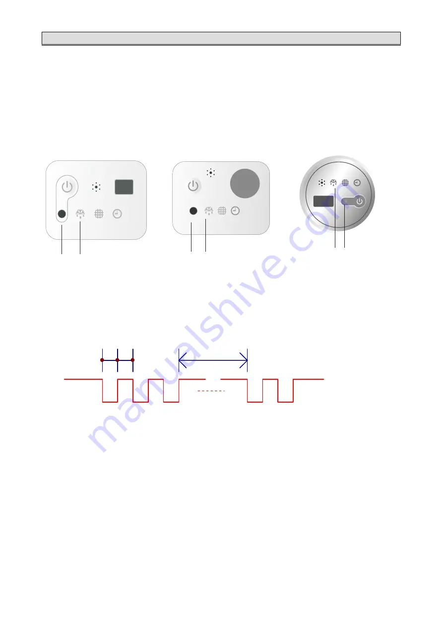
Lamp RUN (LED2, Red) and Lamp DEFROST
(
LED5, Green
)
flash.
Lamp RUN displays
the ten's
place of the
fault
code , lamp DEFROST displays
the unit's place of the
fault code (as shown fig.
below). For example
,
fault code 36: LED RUN & defrost flash 3 times at the
same time, and LED
DEFROST continue flashing 3 times, reports No. 36 fault.
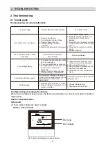
Display panel
1
Run indicator (Red)
Indicates the fault code represented by ten’s place.
2
Defrost indicator (Green)
Indicates the fault code represented by unit’s place.
2 1
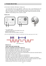
LED FALSH CONTROL flash 300mS (T1) off 300mS(T2), after 2000mS (T3) fault code repeat displays.
(as shown below)
T1 T2
T3
FIG.2 LED flash control
1
2
1
2
1)
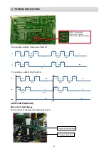
Fault code displayed by LED lamps on outdoor main control board.
There are 3 LED lamps on control board, LED1, LED2 and LED3.
LED1 indicates the ten's place of the fault code, LED2 indicates the unit's place of the fault code and
LED3 indicates outdoor drive control fault.
When LED3 is off, LED1 and LED 2 indicate main control fault code.
When LED3 is on, LED1 and LED 2 indicate drive control fault code.
When LED3 is flickering and LED1, LED 2 are all off, it indicates the compressor is preheating.
Failures display with 5s interval. It means LED will be off for 5s to report the next fault code. System
protection codes display method is the same with main control fault code.
LED lamps will be off when there is no failure, protection or preheating.
Outdoor unit
1.0HP/1.5HP/2.0HP
(9K/12K/18K)
DC-Inverter unitary (Main control board upside-down)
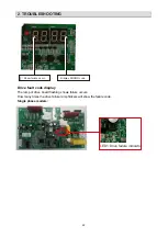
1)
Fault code displayed by LED lamps on outdoor main control board.


