1
.
OPTION LIST
Steps:
①
Leading out wire
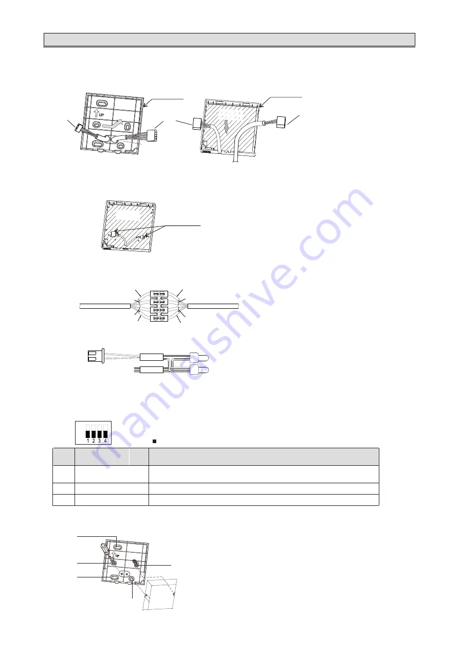
Pull one of the attached controlling cable out of the lower cover from the rear round hole.
* Lead out the wire toward the arrow direction!
Circuit board of
wired controller
lower cover
control cable
RS485
cable
RS485
cable
upper cover
Back outlet hole
Bottom outlet hole
Circuit board of
wired controller
②
Wiring
Wiring terminal
A. Connect the controlling cable with upper cover terminal as the figure above.
B. Connect the attached controlling cable with indoor unit control board.
C. Connect the 2 controlling cables with attached connecting terminal.
D. Connect
RS485 controlling cable (2-pin)
with adaptor(If group control is needed)
.
RS485 controlling cable*
Wire connector*
Firmly fasten the connection cord after connection.
A+: BK
B-: BN
*
attached
with
the adaptor.
YL
YL
WT
RD
RD
BK
BK
Controlling cable
WT
Controlling cable
Note: Symbol “ ” indicates the position of the dip switch.
OFF
ON
S1
Dip
switch
Description
Setting method
S1-1
S1-2
Setting for pull-up/
pull-down resistor
Need to set the switch to ON when wired controller as a primary controller.
S1-3 Setting for terminal resistor Be sure to set the position of the switch on either end of the group control system to “ON”.
S1-4 Setting when fuse is fail to work Set the position of the switch to “ON” to restore the fuse.
5
.
Set the dip switch.
Please dial on the dip switch according to actual situation.
6
.
Securing
the lower cover.
Please secure the lower cover with the attached screws (2 pcs) on the wall or embedded box.
Standard embedded terminal box
Please align the screws with #1 and 3
holes or #1 and 4 holes.
Small-sized embedded terminal box
(86 type)
Please align the screws with #2 and 5
holes.
1
2
5
3
4
2

