18
●
Use special tools and measuring instruments only for the new refrigerant R410A.
●
If vacuum degree -0.1MPa is not available, it is considered that leakage and moisture exist.
(7) Refrigerant Piping Work
1) Confirm that the stop valves of outdoor unit are closed.
2) Connect the indoor unit and the outdoor unit with field-supplied refrigerant piping. Fix the refrigerant piping at certain points
and prevent the refrigerant piping from touching the weak part of the building such as wall, ceiling, etc.( If touched,
abnormal sound may occur due to the vibration of the piping, especially short length piping.)
3) Please connect the piping between indoor and outdoor unit. When tightening the joints of piping, coat inside and outside of
flare piping with a layer of refrigerant oil [Field-supplied (Idemitsu Kosan Co., Ltd. Synthetic oil”FVC68D”)], and use double
spanner to tighten with specific tightening torque. After tightened, please confirm the gas leakage once more. During
brazing, please blow nitrogen into the piping.
4) Before air-tight test, please re-tighten the gas line stop valve spindle.
(a) After flange connection, open the gas line stop valve cap and tighten the spindle with 20 ~ 25 N • m of torque.
(b) Removing the valve cap will cause voice due to slight gas leakage, but the condition is normal.
5) Please perform the air-tight test.
Connect the gauge manifold using charging hoses with a vacuum pump or a nitrogen cylinder to the check joints of the
liquid line and the gas line stop valves. Perform the air-tight test. Apply gas pressure of 4.15MPa.
6) Insulate the unions and flare-nuts at the piping connections completely. Insulate the liquid piping and gas piping completely
to avoid decreasing performance and dewing on the surface of the pipe.
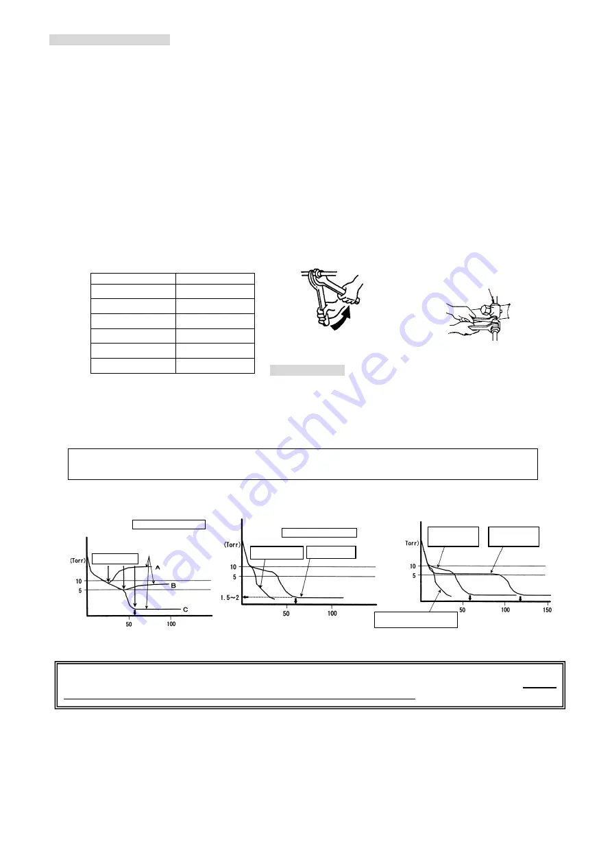
Required Torque
:
(8) Vacuum Work
About the details of stop valve operation, please refer to the nameplate inside service cover.
1) Connect a manifold gauge to the check joints at the both sides. Continue vacuum pumping work until the pressure
reaches-0.1MPa or lower for one to two hours. After vacuum pumping work, shut the manifold valve, stop the vacuum
pump and leave it for one hour.
Check to ensure that the pressure in the manifold gauge does not increase.
2) Because check joints and flare nut cannot be connected, please use the charging hoses. After the work, please tighten the
flare nut with 15~16N • m torque.
3) Vacuum drying determination example
:
Piping Size (mm)
Tightening Torque
¯
6.35(1/4”)
20N
˙
m
¯
9.53(3/8”)
40N
˙
m
¯
12.7(1/2”)
60N
˙
m
¯
15.88(5/8”)
80N
˙
m
¯
19.05(3/4”)
100N
˙
m
Flange With Bolt
53~75 N
˙
m
Please implement vacuum drying determination, to confirm whether moisture exists within the system. If moisture is
present, please extend the vacuum time or install the drying filter until no moisture is present within the system.
Be sure
to do this work, otherwise the unit may be damage easily and difficult to handle.
Vac
uu
m
De
gr
ee
Vacuum Time (min)
Figure1
:
Vacuum Time and Vacuum Degree
Outside air temperature 23°C
Vacuum pump stop
After the vacuum pump
stop, the vacuum degree
rebound phenomenon
Vac
uu
m
De
gr
ee
Figure2
:
Vacuum time and degree with moisture in system
Outside air temperature 20°C
System with
moisture
System without
moisture
Vac
uu
m
De
gr
ee
Vacuum Time (min)
Figure3
:
Outside air temperature vacuum time and degree
System with
moisture, outside air
temperature 20°C
System with
moisture, outside air
temperature 10°C
The system without moisture is not
affected by outside air temperature.
(
Double spanner work
Stop valve tightening work
Do not apply the double spanner work here.
(Refrigerant leakage will occur)
Vacuum Time (min)
Summary of Contents for RAM-10MQ
Page 31: ...31 MEMO ...


