


-30-
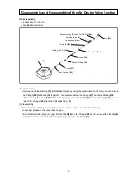
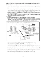
3. Disassembly and reassembly of the Piston Bumper, Feeder (A), Feed Piston, etc
(1) Disassembly
•
Remove the Nose
[47]
and push the lever components from the output section according to item 1 in
"Disassembly and Reassembly of the Nail Feeder Section". You can then remove the Piston Bumper
[45]
.
•
Remove the Retaining Ring For D24 Hole
[114]
by using the C-shaped snap ring puller for the hole, while
pressing the Feed Piston Cover
[113]
with your finger so that it does not pop up. You can then remove the
Feed Piston Cover
[113]
, Bumper
[112]
, Feed Spring (A)
[110]
, and Feed Spring (B)
[111]
.
•
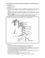
Pull out the Roll Pin D4 x 18
[51]
by using the roll pin puller (ø 4). You can then remove the Feed Piston
[109]
and Feeder Arm (B)
[52]
.
•
Push out the Plunger (B)
[55]
by using the roll pin puller (ø 4). You can then remove Feeder (A)
[54]
and the Feeder Spring
[53]
from Feeder Arm (B)
[52]
.
(2) Reassembly
Conduct reassembly by reversing the disassembly procedure, but note the following:
•
If the air passages of the Body Ass’y
[42]
and Nose
[47]
and the feed piston chamber become clogged
with broken pieces of the Piston Bumper
[45]
or other objects, the Feed Piston
[109]
may not work
properly. So, when replacing the Piston Bumper
[45]
, clean these parts prior to reassembly.
•
Apply grease to the O-Ring (P-9)
[107]
and Feed Piston O-Ring
[108]
prior to reassembly.
•
Apply grease to the groove of the Feed Piston
[109]
.
•
Assemble the Bumper
[112]
with its stepped part on the Feed Piston
[109]
side.
•
Grease must be applied to the sliding parts of the Feed Piston
[109]
and O-Ring of the Nose
[47]
prior
to reassembly. However, too much grease on Surface A will adversely affect Feed Piston
[109]
movement (at low air pressure).
•
Assemble the Roll Pin D4 x 18
[51]
with its split side on the magazine side as shown above. After
reassembly, the amount of protrusion at both ends must match (at 1 to 1.3 mm).
•
Make sure the Retaining Ring For D24 Hole
[114]
is just in the groove of the Nose
[47]
.
Piston Bumper
[45]
Body Ass'y
[42]
Nose
[47]
Feeder Arm (B)
[52]
Feed Piston
[109]
O-Ring (P-9)
[107]
Roll Pin D4 x 18
[51]
Retaining Ring For
D24 Hole
[114]
Feed Piston Cover
[113]
Feed Piston O-Ring (I.D. 14)
[108]
Roll Pin D4 x 18
[51]
Feeder Arm (B)
[52]
Split side
Groove Stepped Groove
Magazine side
Surface
A
Feed piston chamber
Amount of protru
sion:
1 to 1.
3 mm
•
Disassembly and reassembly of Piston Bumper, Feeder (A), Feed Piston, etc


