
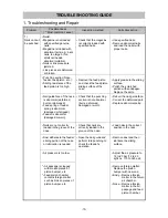


-23-
•
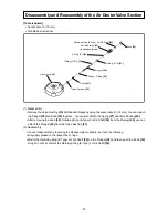
Reassembly of the control valve section
Roll pinholes
Pin groove
Pin groove
Pinholes
Valve Bushing (B)
[88]
concave portion
Valve Bushing (A)
[98]
concave portion
Match these
Valve Bushing (A)
[98]
Valve Bushing (A)
[98]
Plunger
[95]
(2) Reassembly
Conduct reassembly by reversing the disassembly procedure, but note the following:
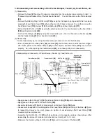
(a) Reassembly of the control valve section
•
Always keep the control valve section clean.
•
Fully apply grease to the O-Ring (S-16)
[87]
, O-Ring (1AP-5)
[96]
and O-Ring (S-6)
[97]
of Valve
Bushing (A)
[98]
, O-Ring (I.D 1.8)
[94]
of the Plunger
[95]
, O-Ring (P7-U)
[89]
, O-Ring (P9-U)
[90]
and O-Ring (1AP-11)
[92]
of the Valve Piston
[91]
, and O-Ring (S-14)
[86]
and O-Ring (S-16)
[87]
of
Valve Bushing (B)
[88]
.
•
Match the concave portion of Valve Bushing (A)
[98]
with that of Valve Bushing (B)
[88]
as shown
below, and then insert the two Pin D2 x 8
[85]
into both. For reassembly on the Body Ass’y
[42]
,
first insert the roll pin puller (ø 3) by making sure the pin passes through the roll pinhole, and then
hammer in the two Roll Pin D3 x 28
[100]
. Orient the splitting of Roll Pin D3 x 28
[100]
as shown
below at reassembly.
NOTE: Always match the roll pin groove of Valve Bushing (A) [98] with the roll pinhole of the
Body Ass’y [42] before hammering in the roll pin. Otherwise, the periphery of Valve
Bushing (A) [98] will be damaged, thereby inhibiting disassembly and reassembly of
the control valve section.
•
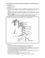
After reassembly, make sure that the Plunger
[95]
moves smoothly.
Roll Pin D3 x 28
[100]
Splitting direction


