--- 27 ---
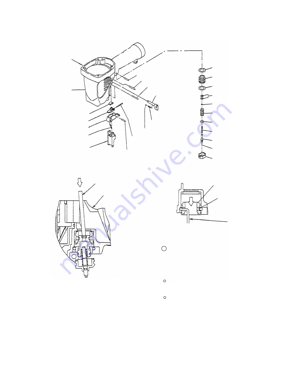
3 Insert a hooked wire into the hole of Valve
Bushing (B) [67] as shown in Fig. 19 and take
out Valve Bushing (B) [67] being careful not to
scratch the inside of Valve Bushing (B) [67].
Be careful not to scratch Valve Piston (B) [70]
and Valve Bushing (B) [67].
Do not pull out the tip of Plunger (A) [73] with
pliers or other tools.
Lock Knob [61]
Body [23]
Trigger Arm (B) [43]
Trigger [45]
Valve Bushing (B) [67]
Head Valve O-ring
(I.D 16.8) [66]
O-ring (S-18) [68]
O-ring (I.D 8.8) [69]
Trigger Piece [41]
Roll Pin D3 x 28 [60]
Lock Spring [63]
Pushing Lever Guide [47]
Trigger Spring [46]
Roll Pin D3 x 28 [60]
Roll Pin D3 x 22 [59]
Retaining Ring (E-type)
for D4 Shaft [21]
Fig. 17 Disassembly and reassembly of the control valve section
Fig. 18
Fig. 19
Steel Ball D3.175 [62]
Spring [42]
Roll Pin D2.5 x 16 [44]
Valve Piston (B) [70]
O-ring (S-4) [55]
O-ring (I.D 11) [71]
Plunger Spring [72]
O-ring (I.D 1.8) [74]
Plunger (A) [73]
Valve Bushing (A) [75]
Rod
Body [23]
Valve Bushing (B) [67]
Hole
Wire
Summary of Contents for NV 65AF3
Page 45: ......


