--- 23 ---
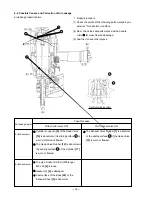
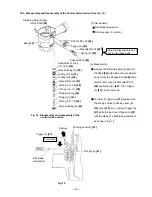
(a) Disassembly
Remove the Retaining Ring (E-type) for
D6 Shaft [20] with blade of a screwdriver
and pull out the Change Knob [50] being
careful not to lose the Steel Ball D3.97
[48] and Spring (C) [49]. Then Trigger
(A) [47] can be removed.
To remove Trigger (A) [47] together with
the driving section (Pushing Lever (B)
[33], Nose [30], etc.), remove Trigger (A)
[47] while forcing down Plunger (A) [61]
with the blade of a flat-blade screwdriver,
as shown in Fig. 15.
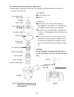
10-3. Disassembly and Reassembly of the Control Valve Section (See Fig. 14.)
Fig. 15
Valve Piston (B) [57]
Plunger Spring [60]
Valve Bushing (A) [63]
Plunger (A) [61]
Head Valve O-Ring
(I.D. 16.8) [53]
Body [22]
Roll Pin D3 x 22 [46]
Retaining Ring (E-type)
for D6 Shaft [20]
O-Ring (I.D. 1.8) [62]
Fig. 14 Disassembly and reassembly of the
control valve section
Trigger (A) [47]
Flat-blade
screwdriver
Plunger (A) [61]
Remove
Pushing Lever (B) [33]
O-Ring (I.D. 11) [59]
O-Ring (I.D. 8.8) [58]
O-Ring (S-4) [56]
O-Ring (S-18) [55]
Valve Bushing (B) [54]
Trigger (A) [47]
Change Knob [50]
[Tools required]
Flat-blade screwdriver
Roll pin puller (3 mm dia.)
Force down
Steel Ball D3.97 [48]
Spring (C) [49]
Carefully disassemble so as
not to lose these parts.
Summary of Contents for NR 90AC3
Page 39: ......


