--- 26 ---
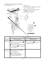
Roll Pin D3 x 28 [51]
Roll Pin D3 x 22 [31]
Body [22]
Collar (B) [29]
Nylock Bolt (W/Flange)
M6 x 20 [27]
Piston Bumper (A) [24]
O-Ring (1AS-60) [26]
Piston Bumper (B) [25]
Hex. Socket Hd.
Bolt M6 x 12 [39]
Pushing Lever (A) [37]
Steel Ball D3.97 [36]
Pushing Lever (B) [33]
Spring [32]
Guard [28]
Nose [30]
Adjuster (A) [34]
Spring (C) [35]
Washer [38]
Magazine section
Nylock Bolt
(W/Flange)
M6 x 20 [27]
Hex.
Socket
Hd. Bolt
M8 x 30
[64]
Connector
[65]
Handle Arm [67]
Pushing Lever (B) [33]
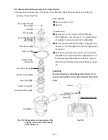
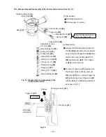
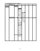
10-4. Disassembly and Reassembly of the Driving Section (See Fig. 19.)
Fig. 19 Disassembly and reassembly of the
drivng section
(b) Reassembly
Disassembly procedures should be followed in the reverse order. Note the following points.
Apply designated grease to the O-ring (1AS-60) [26] and then install it.
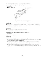
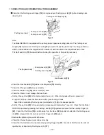
Check that Nail Feeder (B) [75] moves smoothly. Check that the Pushing Lever Stopper [74] is placed over
Pushing Lever (B) [33] when Nail Feeder (B) [75] is at the front end (See Fig. 20.).
Pushing Lever Stopper [74]
Nail Feeder (B) [75]
Fig. 20
[Tools required]
Hex. bar wrench (5 mm and 6 mm)
Roll pin puller (3 mm dia.)
(a) Disassembly
Remove the Nylock Bolt (W/Flange) M6 x 20 [27]
and take out the magazine section.
Remove the Nylock Bolt (W/Flange) M6 x 20 [27]
and take out the Guard [28].
Pull out the Roll Pin D3 x 28 [51] and the Roll Pin
D3 x 22 [31]. Remove the Hex. Socket Hd. Bolt
M8 x 30 [64], then the Nose [30], Pushing Lever
(B) [33] and others can be removed.
Pushing
Lever
Guide [52]
Summary of Contents for NR 90AC3
Page 39: ......


