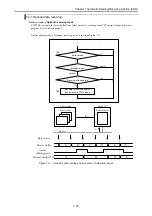
Chapter 7 Automatic Sending/Receiving function (ASR)
7-3
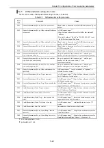
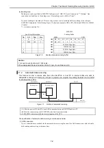
(2). Receiving area
The receiving area can be specified only by “ASR I/O Area (Connection N) Setting” in EH-ETH2 Configurator.
The receiving area can be defined every ASR connection. Available I/Os are word I/Os except WX.
EH-ETH2
CPU
module
Receive Area Information
Receiving buffer
I/O
Receiving area
No. I/O Top Size
H00
DT1
WR0
DT1 DT2
1 WR 0 10 H01
DT2
WR1
DT3 DT4
H02
DT3
WR2
DT5 DT6
H03
DT4
WR3
DT7 DT8
…
…
…
… …
H12
DT19
WR8
DT17 DT18
H13
DT20
WR9
DT19 DT20
20
Byte
10
Word
Figure 7.4
Receiving area and receiving buffer (1)
Caution
- 1 connection can handle up to 1454 bytes.
- When received data size is less than designated receiving area size, the rest area is not overwritten. The
previous data is kept.
- When received data size is bigger than designated receiving data size, the excess area is omitted
automatically.
Receive Area Information
Receiving buffer
I/O
Receiving area
No. I/O Top Size
H00
DT1
WR0
DT1 DT2
1 WR 0 10 H01
DT2
WR1
DT3 DT4
H02
DT3
…
… …
H03
DT4
WR6
DT13 DT14
…
…
WR7
DT15
DT16
H0E
DT15
WR8
DT(n+1)
DT(n)
H0F
DT16
WR9
DT(n+3)
DT(n+2)
16
Byte
10
Word
: Previous received data
Figure 7.5
Receiving area and receiving buffer (2)
Receive Area Information
Receiving buffer
I/O
Receiving area
No. I/O Top Size
H00
DT1
WR0
DT1 DT2
1 WR 0 10 H01
DT2
WR1
DT3 DT4
H02
DT3
WR2
DT5 DT6
H03
DT4
WR3
DT7 DT8
…
…
…
… …
H1E
DT31
WR8
DT17 DT18
H1F
DT32
WR9
DT19 DT20
32
Byte
10
Word
: excess data
Figure 7.6
Receiving area and receiving buffer (3)


