Chapter 8 Register Structure
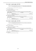
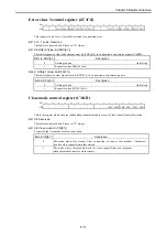
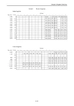
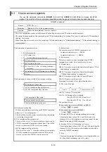
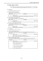
WY data register (WYs1)
Bit
15
14
13
12
11
10 9 8 7 6 5 4 3 2 1 0
+0
- APR A6R A5R A4R
A3R
A2R
A1R
T4R
T3R
T2R
T1R -
- EC1 EC0
Bit 15: Reserved
This bit are reserved. Please set "0" always.
Bit 14: All Ethernet port reset bit (APR)
This bit is used to reset the all ethernet port.
Bit14: APR
Description
0
Nothing is done.
(Initial set)
1
All ethernet port (task code port No.1 to 4 and ASR port No.1 to 6) are reset.
Bit 13 to 8: ASR port reset bit (A6R to A1R)
This bit is used to reset ASR port No.1 to 6 individually.
Bit13 - 8:AnR
Description
0
Nothing is done.
(Initial set)
1
ASR port No.n (1 to 6) is reset.
Bit 7 to 4: Task code port reset bit (T4R to T1R)
This bit is used to reset task code port No.1 to 4 individually.
Bit7 - 4:TnR
Description
0
Nothing is done.
(Initial set)
1
Task code port No.m (1 to 4) is reset.
Bit 2, 3: Reserved
These bits are reserved. Please set "0" always.
Bit 1: IER LED indication/Clear bit (EC1)
This bit is used to turn IER LED off. And also this bit clear IERR bit of Module status register bit1.
Bit1: EC1
Description
0
Nothing is done.
(Initial set)
1
Request to turn IER LED off and clear IERR bit to "0".
Bit 6 of CnESR : clear ASR table set-up error bit (ATE) to "0".
Bit 0: ERR LED indication/Clear bit (EC0)
This bit is used to turn ERR LED off. And also this bit clear ERR bit of Module status register bit0.
Bit0: EC0
Description
0
Nothing to done.
(Initial set)
1
Request to turn ERR LED off and clear ERR bit to "0".
Clear the following bits of CnESR.
Bit 0 : Open error bit (OE)
Bit 1 : Send timeout error bit (STE)
Bit 3 : Receive area error bit (RAE)
Bit 4 : Receive error bit (RCE)
Bit 5 : Send error bit (SNE)
8-24

