3-9
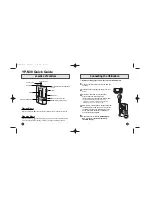
FLOW CHART NO.3
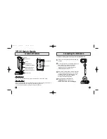
FLOW CHART NO.4
Cassette tape can not be loaded.
Cassette tape is ejected right after the loading.
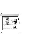
FLOW CHART NO.5
Cassette tape can not be ejected.
When loading a cassette tape, on Pin(69) of
IC501, does the "L" pulse switch to the "H" pulse?
When loading a cassette tape, on Pin(69) of IC501,
does the "L" pulse switch to the "H" pulse?
When loading a cassette tape, on Pin(62) of IC501,
does the "L" pulse switch to the "H" pulse?
When pressing the eject button, does the Capstan
Motor start rotating?
Refer to "FLOW CHART NO.6 " <The Capstan
Motor does not rotate>.
Check the Reel Disc or Clutch Assembly, etc., and
service it if defective.
Replace IC501.
Replace the Capstan Motor.
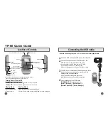
Replace the Loading Motor.
While the Capstan Motor is rotating, is the Takeup
Reel rotating?
Is the Loading Motor rotating?
Check the Cam Gear or Rack Assembly, etc,
and service it if defective.
While the Takeup Reel is rotating, is the reel pulse
signal inputted to Pin(3) of IC501?
While the reel pulse signal is inputting, is "L" pulse
inputted to Pin(21) of IC501?
Is the specified voltage (approximately 13V)
outputted to the terminal of the Lading Motor?
When loading a cassette tape, does the LD-SW
operate normally?
When loading a cassette tape, is the specified
voltage (approximately 13V) outputted to the
terminal of the Loading Motor Unit?
Check the line between the start sensor and
Pin(69) of IC501, and service it if defective.
Replace the Capstan Motor Unit.
Replace the Loading Motor Unit.
Replace IC501.
Yes
Yes
Yes
Yes
Yes
Yes
Yes
Yes
Yes
Yes
Yes
No
Check the line between the start sensor and
Pin(69) of IC501, and service it if defective.
Check the line between the end sensor and
Pin(62) of IC501, and service it if defective.
Check the line between the LD-SW(SW512) and
Pin(68) of IC501, and service it if defective.
Check the line between the Takeup Reel sensor
and Pin(3) of IC501, and service it if defective.
No
No
No
No
No
No
No
No
No
No
Summary of Contents for DV-PF35U
Page 79: ...S 5 S 4 Main 1 8 Schematic Diagram ...
Page 81: ...S 7 S 6 Main 3 8 Schematic Diagram ...
Page 82: ...S 8 S 7 Main 4 8 Schematic Diagram ...
Page 83: ...S 9 S 8 Main 5 8 Schematic Diagram ...
Page 84: ...S 10 S 9 Main 6 8 DVD Open Close Schematic Diagram ...
Page 86: ...S 12 S 11 Main 8 8 Schematic Diagram ...
Page 88: ...S 14 S 13 DVD Main 2 3 Schematic Diagram ...
Page 90: ...S 16 S 15 DVD Main 3 3 Schematic Diagram ...
Page 102: ...DV PF35U No 0508E TK Digital Media Division Yokohama ...