4-5
4-4-2. Tape Interchangeability Alignment
Note:
To do these alignment procedures, make sure that the
Tracking Control Circuit is set to the preset position
every time a tape is loaded or unloaded. (Refer to
page 4-7, procedure 1-C, step 2.)
Equipment required:
Dual Trace Oscilloscope
VHS Alignment Tape (MH-1)
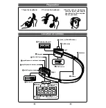
Guide Roller Adj. Screwdriver
Flat Screwdriver (Purchase Locally)
Note: Before starting this Mechanical Alignment, do all
Electrical Adjustment procedures.
Adjust the X Value for maximum envelope.
(Page 4-6) (Use Alignment Tape.)
Check to see that the tape is not creasing
and that there is no slack on the supply
and take-up side Guide Rollers.
(Use a blank tape.)
Adjust the height of the Guide Rollers
(Supply side and take-up side).
(Use a blank tape.) (Page 4-6)
Loading (Use a blank tape.)
Adjust the envelope. (Page 4-7)
Check the envelope.
Adjust the Audio Section.
(Azimuth Alignment) (Page 4-8)
Check the audio output.
Check the following:
1. X Value (Page 4-6)
2. Envelope (Page 4-7)
Adjust the X value and envelope.
Not good
Do the final tape-traveling test to see that
the tape runs normally in play mode with-
out creasing or slacking.
Completion
Not good
OK
OK
OK
Not good
Not good
OK
Flowchart of Alignment for tape traveling
1-A
1-A
1-B
1-C
1-C
1-D
1-D
1-B, 1-C
1-B, 1-C
1-A
Summary of Contents for DV-PF35U
Page 79: ...S 5 S 4 Main 1 8 Schematic Diagram ...
Page 81: ...S 7 S 6 Main 3 8 Schematic Diagram ...
Page 82: ...S 8 S 7 Main 4 8 Schematic Diagram ...
Page 83: ...S 9 S 8 Main 5 8 Schematic Diagram ...
Page 84: ...S 10 S 9 Main 6 8 DVD Open Close Schematic Diagram ...
Page 86: ...S 12 S 11 Main 8 8 Schematic Diagram ...
Page 88: ...S 14 S 13 DVD Main 2 3 Schematic Diagram ...
Page 90: ...S 16 S 15 DVD Main 3 3 Schematic Diagram ...
Page 102: ...DV PF35U No 0508E TK Digital Media Division Yokohama ...