--- 23 ---
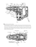
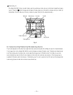
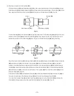
Fig. 17
Slide Sleeve (B)
[33]
Piston
[44]
Slide Ring
[30]
Crank Case
[94]
Slide Sleeve (A)
[34]
Cylinder
[36]
Crank Shaft
[92]
Connecting Rod
[45]
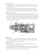
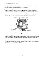
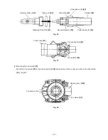
(4) Removal of the Piston
[44]
The Piston
[44]
is remainded in the Crank Case
[94]
. Move the Crank Shaft
[92]
to the bottom dead center
then the piston ass'y can be removed from the Crank Shaft
[92]
. (Figs. 18 and 19)
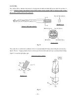
Fig. 18
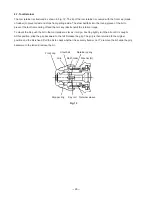
Crank Case
[94]
Crank Shaft
[92]
Connecting
Rod
[45]
Fig. 19
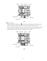
(5) Removal of the First Gear
[98]
and the Crank Shaft
[92]
Remove the Hex. Socket Hd. Bolt (W/Flange) M5 x 16
[102]
and the Tapping Screw (W/Flange) D5 x 20
(Black)
[103]
from Handle (A). (B) Set
[101]
and separate Handle (A). (B) Set
[101]
from the Crank Case
[94]
and the Housing Ass'y
[106]
. Remove the Seal Lock Hex. Socket Hd. Bolt M6 x 45
[54]
from the Crank Case
[94]
and separate the Crank Case
[94]
from the Housing Ass'y
[106]
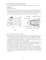
. Place the Crank Case
[94]
on a support
facing the Connecting Rod
[45]
downward and press the end face of the Crank Shaft
[92]
with a hand press to
remove the Crank Shaft
[92]
and the First Gear
[98]
. (Fig. 20)


