--- 22 ---
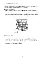
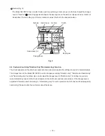
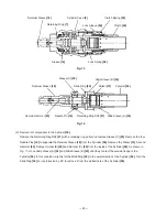
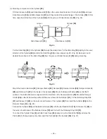
Fig. 15
Retaining Ring
[7]
Sleeve
[16]
Retainer Sleeve
[18]
Lock Spring
[38]
Lock Sleeve
[39]
Cylinder Case
[9]
Clutch Spring
[35]
Clutch
[40]
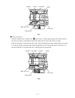
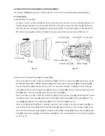
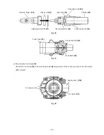
Fig. 16
Slide Ring
[30]
Second Hammer
[23]
Retainer Sleeve
[18]
Retaining Ring D38
[21]
Sleeve (C)
[20]
Cylinder
[36]
Striker
[31]
Slide Sleeve (A)
[34]
Slide Sleeve (B)
[33]
Needle Pin
[19]
(3) Removal of components in the Cylinder
[36]
Remove the Retaining Ring D38
[21]
with a retaining ring puller and remove Sleeve (C)
[20]
. Remove the four
Needle Pins
[19]
to separate the Retainer Sleeve
[18]
from the Cylinder
[36]
. Remove the Striker
[31]
, Second
Hammer
[23]
, Damper Holder (B)
[28]
and Damper (C)
[29]
from the inside of the Cylinder
[36]
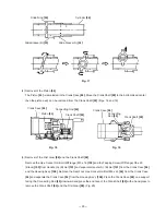
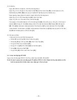
. As shown in
Fig. 17, move Slide Sleeve (A)
[34]
and Slide Sleeve (B)
[33]
until they contact the outside flange of the
Cylinder
[36]
. In this condition, slightly tilt the Slide Ring
[30]
to the axial direction of the Cylinder
[36]
. Turn the
Slide Ring
[30]
on its protrusion by 90
û
to remove it from the slotted hole of the Cylinder
[36]
.


