-8-
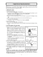
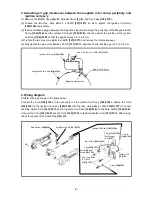
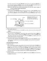
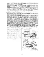
Hex. Hole Bolt 4 x 18WS
[127]<127>
Ignition Coil Ass'y
[128]<128>
Magneto Rotor Comp.
[136]<136>
Magnetic steel portion
Gap 0.3 to 0.4 mm
3. Adjusting air gap (clearance) between the magneto rotor comp. periphery and
ignition coil ass'y
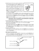
(1) Remove the Muffler Cover
[4]<4>
, Cylinder Cover
[1]<1>
, and Fan Case
[118]<118>
.
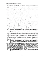
(2) Loosen the two Hex. Hole Bolts 4 x 18WS
[127]<127>
so as to tighten the Ignition Coil Ass'y
[128]<128>
temporarily.
(3) Insert a thickness gauge between the magnetic steel section along the periphery of the Magneto Rotor
Comp.
[136]<136>
and the Ignition Coil Ass'y
[128]<128>
, and then adjust the position of the Ignition
Coil Ass'y
[128]<128>
so that the gap becomes 0.3 to 0.4 mm.
(4) Tighten the two Hex. Hole Bolts 4 x 18WS
[127]<127>
and remove the thickness gauge.
(5) Fully tighten the Hex. Hole Bolts 4 x 18WS
[127]<127>
, and then check that the gap is 0.3 to 0.4 mm.
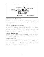
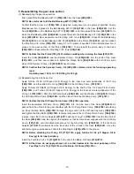
4. Wiring diagram
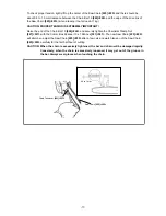
Perform wiring as shown in the figure below.
Connect the Cord
[134]<134>
to the connector on the Ignition Coil Ass'y
[128]<128>
. Fasten the Cord
[135]<135>
to the Ignition Coil Ass'y
[128]<128>
with the Hex. Hole Bolts 4 x 18WS
[127]<127>
. Connect
the Stop Switch Cord
[107]<107>
and the Ignition Coil Ass'y
[128]<128>
to the Stop Switch
[106]<106>
.
Connect the Cord
[134]<134>
and the Cord
[135]<135>
to the Stop Switch Cord
[107]<107>
. After wiring,
check for sparks of the Spark Plug
[12]<12>
.
Stop Switch Cord
[107]<107>
Stop Switch
[106]<106>
Cord
[134]<134>
Ignition Coil Ass'y
[128]<128>
Hex. Hole Bolts
4 x 18WS
[127]<127>
Cord
[135]<135>
Cord
[133]<133>
Earth Cord
[130]<130>
Screw
[129]
or
Screw M4
<129>
M4 Flange
Nut
[132]
Clip
[131]<131>
Washer T1.6
[16]<16>

