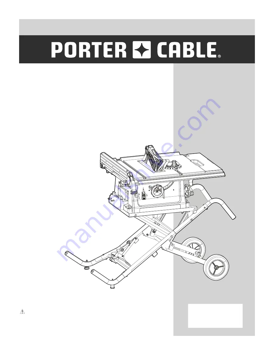
background image

10 IN. (254 mm) 
JOBSITE TABLE SAW

ScIE cIrcuLAIrE dE 254 mm 
(10 pO) Sur LE LIEu dE TrAvAIL

SIErrA dE mESA dE 254 mm 
(10 puLg.) pArA LA OBrA

cATALOg NumBEr

pcB222TS

Instruction manual

Manuel d’instructions
Manual de instrucciones

www.portercable.com

INSTRUCTIVO DE OPERACIÓN, CENTROS DE 
SERVICIO Y PÓLIZA DE GARANTÍA.  
    

AdvErTENcIA:

 LÉASE ESTE INSTRUCTIVO 

ANTES DE USAR EL PRODUCTO.

Summary of Contents for PCB222TS

Page 1: ...ail sierra de mesa de 254 mm 10 pulg para la obra CATALOG NUMBER PCB222TS Instruction Manual Manuel d instructions Manual de instrucciones www portercable com INSTRUCTIVO DE OPERACIÓN CENTROS DE SERVICIO Y PÓLIZA DE GARANTÍA ADVERTENCIA LÉASE ESTE INSTRUCTIVO ANTES DE USAR EL PRODUCTO ...

Page 2: ...e connected to a 110 120 Volt 15 Ampere time delay fuse or circuit breaker To avoid shock or fire replace power cord immediately if it is worn cut or damaged in any way Before using your table saw it is critical that you read and understand these safety rules Failure to follow these rules could result in serious injury to you or damage to the table saw MOTOR Type universal Amps 15 Voltage 120 Hz 6...

Page 3: ...th eyes or lay on the skin may promote absorption of harmful chemicals Use of this tool can generate and or disperse dust which may cause serious and permanent respiratory or other injury Always use NIOSH OSHA approved respiratory protection appropriate for the dust exposure Direct particles away from face and body WARNING WARNING safety guidelines definitions SAFETY ALERT Precautions that involve...

Page 4: ...ll cause the tool to overheat The table on page 8 shows the correct size to use depending on cord length and nameplate WARNING ampere rating If in doubt use the next heavier gauge The smaller the gauge number the heavier the cord 11 WEAR PROPER APPAREL Do not wear loose clothing gloves neckties rings bracelets or other jewelry which may get caught in moving parts Nonslip footwear is recommended We...

Page 5: ...lubricating and changing accessories 23 DO NOT use power tool in presence of flammable liquids or gases power tool safety 24 DO NOT operate the tool if you are under the influence of any drugs alcohol or medicationn that could affect your ability to use the tool properly 25 Dust generated from certain materials can be hazardous to your health Always operate saw in well ventilated area and provide ...

Page 6: ...own back towards you by keeping the blade sharp the rip fence parallel to the saw blade and by keeping the riving knife anti kickback pawls and guards in place aligned and functioning Do not release work before passing it completely beyond the saw blade Do not rip work that is twisted warped or does not have a straight edge to guide it along the fence 14 AVOID AWKWARD OPERATIONS and hand positions...

Page 7: ...ect and rises from the table and is thrown toward the operator Kickbacks can be avoided by attention to the following conditions How to Avoid Them and Protect Yourself from Possible Injury a Be certain that the rip fence is parallel to the saw blade b Do not rip by applying the feed force to the section of the workpiece that will become the cut off free piece Feed force when ripping should always ...

Page 8: ...n Use a seperate electrical circuit for your tool Your table saw is wired at the factory for 120V operation Connect to a 120V 15 Amp circuit and use a 15 Amp time delay fuse or circuit breaker To avoid shock or fire if power cord is worn cut or damaged in any way have it replaced immediately GROUNDING INSTRUCTIONS This tool must be grounded while in use to protect the operator from electrical shoc...

Page 9: ...eceptacle box In all cases make certain the receptacle is properly grounded If you are not sure have a qualified electrician check the receptacle CAUTION Fig 1 Fig 2 Three Pronged Plug Grounding Prong Properly Grounded Three Pronged Receptacle Grounding Lug Make sure this is connected to a known ground Two Pronged Receptacle Adapter ...

Page 10: ...do not attempt to assemble the table saw or plug in the power cord until the missing or damaged part is correctly replaced TABLE OF LOOSE PARTS WARNING Flat bladed screwdriver Adjustable wrench and 10 13 14 17 mm wrench Phillips screwdriver Straight edge Combination square Blade wrench Blade wrench ITEM DESCRIPTION QUANTITY A Handwheel handle hardware bag 1 B Rear table extension 1 C Rear extensio...

Page 11: ...11 A B C D E F G H I J K L M N O P Q UNPACKING YOUR JOBSITE TABLE SAW R S T U V ...

Page 12: ...k storage Riving knife Blade guard storage Side table extension Blade bevel lock handle Miter gauge Blade guard ON OFF switch with key Blade elevation handwheel Blade tilting handwheel Stand Foot pedal Anti kickback pawls Adjustable foot pad Overload reset button Rip fence storage Stand handles Mounting hole Table insert ...

Page 13: ...f the blade It helps make accurate straight or angle crosscuts NON THROUGH SAWING Refers to any cut that does not completely cut through the workpiece OVERLOAD RESET SWITCH Protects the motor if it overloads during operation provides a way to restart the saw PUSH STICK Used to push workpieces when performing ripping operations PUSH BLOCK Used for ripping operation when the workpiece is too narrow ...

Page 14: ...hown in Fig A 1 NOTE This is the leg tube with the welded nut on the bend area of the leg tube 6 Tighten with a phillips screwdriver and 10 mm wrench 7 Repeat steps 5 6 for assembling the other stand leg tube 4 into the straight stand leg 8 Assemble the foot pad 5 with the bolt 6 and nut 7 in the other stand leg tube 4 9 Assemble the adjustable foot pad 8 with the wing nut 9 and thread onto the we...

Page 15: ...position Fig E SETTING UP THE STAND FIG B B 1 1 Lift up the stand to its vertical position as shown in step 1 of Fig B 2 Unfold the stand by stepping on the foot pedal 1 to release the locking treadle hook 2 and press down on stand handle until the stand is in its lowest position NOTE You should hear a click when locked in place Fig B Fig B 1 For your safety never connect plug to power source rece...

Page 16: ...2 Slide the assembly forward locking into place Fig I 2 1 3 1 2 3 ADJUSTING THE TABLE INSERT FIG F To avoid serious injury the table insert 2 must be level with the table If the table insert is not flush with the table adjust the four bolts 1 with a 4 mm hex wrench until it is parallel with the table NOTE To raise the insert turn the hex screws counterclockwise To lower the insert turn the hex scr...

Page 17: ...levation rod 2 at the front of the saw Make sure the slots 3 in the hub of the handwheel 1 engage with the pins 4 on the saw 2 Attach and tighten the crown nut 5 using a 13 mm wrench 2 1 2 1 Anti kickback pawls storage Fig J Storage for the anti kickback pawls 1 is located on the right side of the saw housing 1 Place the anti kickback pawls 1 on the bracket 2 for storing make sure the protrusion 3...

Page 18: ...2 5 6 4 Fig N INSTALLING THE BLADE TILTING HANDWHEEL FIG O NOTE 0 45 is printed on this handwheel 1 Bag A _ Attach the blade tilting handwheel 1 to the blade tilting rod on the right side of the saw in the same manner as you attached the elevation handwheel 2 Attach and tighten the crown nut 2 using a 13 mm wrench Fig O INSTALLING THE REAR OUTFEED SUPPORT FIG P Q 1 Bag B C D _ Insert one tube 2 in...

Page 19: ...ine if the blade is 90 to the table Fig U 5 If the blade is not 90 to the table loosen the two set screws 4 located on the collar 5 underneath the table saw with the 3 mm hex key and back off the collar Fig V 6 Loosen the blade bevel lock handle turn the blade tilting handwheel to move the blade until it is 90 to the table and tighten the blade bevel lock handle 7 Adjust the collar 5 so it contact...

Page 20: ...arked tooth 9 If the ruler touches the marked tooth at the front and rear position no adjustment is needed at this time If not or the base of the ruler is no longer parallel with the edge of the miter gauge groove perform adjustment procedure described in next section Fig W WARNING WARNING 2 1 Fig U Fig V 45 Stop 1 With the blade in the upright 90 position loosen the blade bevel lock handle and mo...

Page 21: ...move the trunnion 2 toward the right or left side until the blade is parallel to the miter gauge slot and then securely tighten the two bolts counterclockwise 3 If the blade is still not parallel to the miter gauge slot loosen the two alignment bolts 3 clockwise located on the underside of the table at the rear of the saw 4 Carefully move the trunnion 4 toward the right or left side until the blad...

Page 22: ... the factory but it should be rechecked and adjusted if necessary 1 Remove the table insert and raise the blade to the maximum height with the blade elevation handwheel 2 Remove the blade guard and anti kickback pawls assembly after first time riving knife installation 3 Adjust the blade to the 0 vertical position by unlocking the blade bevel lock handle and turning the blade tilting handwheel cou...

Page 23: ... the locking lever 2 located on top Fig BB 3 Place the front of assembly into slot 3 and push down making sure the assembly is engaged in the slots Push down on the locking lever 2 to lock Fig BB CC NOTE Make sure the anti kickback pawls assembly is locked in position before operating saw Fig BB Fig CC 4 Take the blade guard 4 and press down on the red spring button 5 located on the top of assembl...

Page 24: ...ard and anti kickback pawls in place aligned and functioning Do not release the work before passing it completely beyond the saw blade Do not rip work that is twisted warped or does not have a straight edge to guide it along the fence Do not attempt to back out of a cut with the blade running Improper riving knife alignment can cause kickback and serious injury Fig FF Never use a rip fence and mit...

Page 25: ...the adjusting nut 5 clockwise using a 10 mm wrench until the rear clamp is snug Do not turn the adjusting screw more than 1 4 turn at a time Over tightening the adjusting screw will cause the fence to come out of alignment Failure to properly align the fence can cause kickback and serious injury could occur Fig II RIP FENCE INDICATOR ADJUSTMENT FIG JJ NOTE The rip fence indicator points to the sca...

Page 26: ...a power failure blown fuse or tripped circuit breaker turn the switch OFF and remove the key preventing an accidental startup when power comes on Fig NN OVERLOAD PROTECTION FIG MM This saw has an overload reset button 4 that resets the motor after it shuts off due to overloading or low voltage If the motor stops during operation turn the ON OFF switch to the O OFF position and unplug the saw Wait ...

Page 27: ...scutting Ripping is cutting along the length and the grain of the workpiece Crosscutting is cutting either across the width or across the grain of the workpiece It is not safe to rip or crosscut by freehand Ripping requires the use of the rip fence and crosscutting requires the miter gauge NEVER USE THE TWO AT THE SAME TIME Before using the saw each time check the following 1 The blade is tightene...

Page 28: ...iece Never attempt to pull the workpiece backwards during a cutting operation This will cause kickback and serious injury to the user can occur When the blade completely stops raise the anti kickback pawls 7 on each side of the riving knife and slide the workpiece out BEVEL RIPPING This cut is the same as ripping except the blade bevel angle is set to an angle other than 0 RIPPING SMALL PIECES To ...

Page 29: ...e on the table when crosscutting and or bevel crosscutting to avoid instability WARNING Make sure the screw heads do not stick out from the bottom of the base they must be flush or recessed The bottom must be flat and smooth enough to rest on the saw table without rocking Fig UU PUSH BLOCK Use for ripping operation when the workpiece is too narrow to use a push stick Always use a push block for ri...

Page 30: ...e 3 Tighten the miter lock handle 2 at 90 4 Hold workpiece 3 firmly against the face of the miter gauge throughout the cutting operation Fig YY COMPOUND MITER CROSSCUTTING FIG ZZ 0 45 BLADE BEVEL 0 45 MITER ANGLE Always work to the right side of the blade during this type of cut The miter gauge must be in the right side groove because the bevel angle may cause the blade guard to interfere with the...

Page 31: ...with C clamps 3 to fasten the workpiece securely 4 Mount the auxiliary fence 4 with C clamps 5 Use the push block 2 to move the workpiece NOTE Mount the featherboard to table as shown so the leading edges of featherboard will help workpiece complete cutting Fig cc DADO CUTS FIG dd ee Only Stackable dado blades can be used on this saw DO NOT use Adjustable or Wobble type dadoes The maximum dado cut...

Page 32: ...n in the dado set s instruction manual Blade or chipper must not exceed 1 2 inch 12 7 mm 7 Check saw to ensure that the dado will not strike the housing insert or motor when in operation Fig dd For your own safety always replace the blade blade guard assembly anti kickback pawls assembly riving knife assembly and table insert after finishing a dado operation Fig ee Dado Cut ...

Page 33: ...ized service centers or other qualified service organizations always using identical replacement parts WARNING WARNING WARNING LUBRICATION Ball bearings in the table saw are packed with grease at the factory and require no further lubrication REPLACING THE CARBON BRUSHES FIG ff Always disconnect the plug from the power source before inspecting the brushes The carbon brushes included with the unit ...

Page 34: ...ice Be sure to include all of the information shown on the nameplate of your tool model number type serial number etc WARNING PROBLEM POSSIBLE CAUSES CORRECTIVE ACTION Saw will not start 1 Saw is not plugged in 2 Fuse blown or circuit breaker tripped 3 Cord is damaged 1 Plug in saw 2 Replace fuse or reset circuit breaker 3 Have cord replaced by Porter Cable Service Center or Authorized Service Sta...

Page 35: ...nstall and use rip fence 4 Install and use riving knife with guard 5 Replace blade 6 Push material all the way past saw blade before releasing work 7 Tighten the handle Blade does not raise or tilt freely 1 Sawdust and dirt in elevation tilting mechanisms 1 Brush or blow out loose dust and dirt Blade does not come up to speed Reset trips too easily 1 Extension cord too light or too long 2 Low hous...

Page 36: ...s available from your Porter Cable Factory Service Center or a Porter Cable Authorized Warranty Service Center Please visit our Web Site www portercable com for a catalog or for the name of your nearest supplier Do not use any accessory unless you have completely read the Instruction Manual for that accessory To avoid the risk of personal injury Do not use a dado with a diameter larger than 6 in 1...

Page 37: ...plywood or solid wood Use 1 2 in 13 mm or 3 4 in 19 mm material Push stick MUST be thinner than the width of material being cut Drill Hole for Hanging Notch for Prevent Hand from Slipping Cut Here to Push 1 2 in 13 mm Wood Cut Here to Push 3 4 in 19 mm Wood PUSH STICK PATTERN ...

Page 38: ...43 NOTEs ...

Page 39: ...so trademarks for one or more Porter Cable and Delta products 2 BY 4 890TM Air America AIRBOSSTM Auto Set B O S S Bammer Biesemeyer Builders Saw Charge Air Charge Air Pro CONTRACTOR SUPERDUTY Contractor s Saw Delta DELTA Delta Industrial DELTA MACHINERY DESIGNTM Delta Shopmaster and Design Delta X5 Deltacraft DELTAGRAM Do It Feel it DUAL LASERLOC AND DESIGN EASY AIR EASY AIR TO GOTM ENDURADIAMOND ...

Reviews: