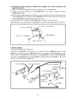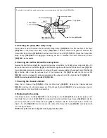
-14-
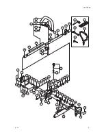
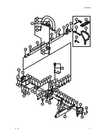
4. Disassembling the gear case section
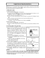
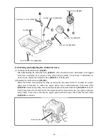
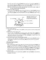
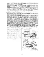
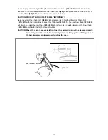
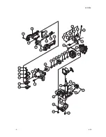
(1) Slightly loosen the Chain Bar Clamp Nut
[227]<227>
while being careful not to remove it.
Turn the Oil Pump Adjuster
[217]<217>
counterclockwise to decrease the tension of the Saw Chain
[225]<225>
.
NOTE: Turning the Oil Pump Adjuster [217]<217> counterclockwise decreases the tension of
the Saw Chain [225]<225>; turning it clockwise increases the tension.
(2) Remove the Chain Bar Clamp Nut
[227]<227>
and the Side Cover Comp.
[207]<207>
, and then
remove the Chain Bar 10
[226]<226>
and the Saw Chain
[225]<225>
.
Loosen the Hex. Hole Bolt 5 x 22/S
[190]<190>
and the Hex. Hole Bolt 5 x 10
[198]<198>
, and then
remove the gear case ass’y from the Main Pipe Comp.
[170]<170>
.
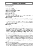
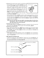
(3) Open the Oil Tank Cap Ass’y
[188]<188>
and then drain out the chain oil from the oil tank.
Remove the four Small Screws 4 x 12WS
[209]<209>
, and then remove the four Collars 3
[210]<210>
,
Oil Tank Cover
[176]<176>
, and Oil Tank Gasket
[177]<177>
.
Remove Stop Ring E-6
[218]<218>
and turn the Oil Pump Adjuster
[217]<217>
(with O-ring P-5
[178]<178>
) counterclockwise to remove the adjuster.
Turn the Step Bolt A
[180]<180>
(with the O-ring P-5
[178]<178>
and the 8 Push Nut
[179]<179>
)
counterclockwise to remove the Step Bolt A
[180]<180>
.
(4) Remove the Oil Pump Comp.
[181]<181>
together with the Filter Ass’y
[211]<211>
, Fuel Pipe 3 x 5 x
60
[214]<214>
, Fuel Pipe 3 x 5 x 75
[215]<215>
, O-ring
[182]<182>
, O-ring 1.4
[183]<183>
, Washer
2
[184]<184>
, Oil Pump Spring
[185]<185>
, and Oil Pump Piston Comp.
[186]<186>
.
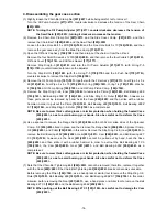
(5) Remove the Stop Ring C-24, Inner
[196]<196>
to remove the Pinion
[192]<192>
, Ball Bearing 609
[193]<193>
, Ball Bearing 609Z ST
[194]<194>
, and Stop Ring C-9, Outer
[195]<195>
; however, as
these parts cannot be removed by hand, heat the Case
[220]<220>
and then strike with a rubber
hammer in order to pull out the Pinion
[192]<192>
, Ball Bearing 609
[193]<193>
, Ball Bearing 609Z
ST
[194]<194>
, and Stop Ring C-9, Outer
[195]<195>
as a complete set.
NOTE: Be sure to wear thick cotton gloves or similar protection when holding the heated Case
[220]<220>, so as to avoid burning your hands. Also be careful not to deform the Case
[220]<220>.
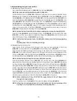
(6) Use a spanner to remove the Flange Nut 6
[206]<206>
with both 32 mm wide sides of the Sprocket
Comp., 3/8
[205]<205>
fixed in place, and then remove the Flange Nut 6
[206]<206>
, Sprocket Comp.,
3/8
[205]<205>
, and Collar
[204]<204>
in this order. Remove the Stop Ring C-28, Inner
[203]<203>
to
remove the Ball Bearing 638Z
[202]<202>
, Gear
[201]<201>
, Cam
[200]<200>
, and Ball Bearing 627
C3
[199]<199>
; however, as the Gear
[201]<201>
cannot be pulled out by hand, heat the Case
[220]<220>
and then strike it with a rubber hammer in order to pull out the Ball Bearing 627 C3
[199]<199>
, the Cam
[200]<200>
, Gear
[201]<201>
, and Ball Bearing 638Z
[202]<202>
as a
complete set.
NOTE: Be sure to wear thick cotton gloves or similar protection when holding the heated Case
[220]<220>, so as to avoid burning your hands. Also be careful not to deform the Case
[220]<220>.
(7) Note that the Chain Bar Tightening Bolt
[222]<222>
cannot be removed; therefore, replace it together
with the Case
[220]<220>
if the Chain Bar Tightening Bolt
[222]<222>
breaks or becomes unusable.
Before removing the Pinion
[192]<192>
, use a hand press or similar tool to remove the Stop Ring C-9,
Outer
[195]<195>
, Ball Bearing 609
[193]<193>
, and Ball Bearing 609Z ST
[194]<194>
in this order.
Likewise, before removing the Gear
[201]<201>
, use a hand press or similar tool to remove the Ball
Bearing 627 C3
[199]<199>
and the Ball Bearing 638Z
[202]<202>
.
NOTE: When pulling out the Ball Bearing 627 C3 [199]<199>, be careful not to damage the Cam
[200]<200>.

