background image

4. Operation 

4-20 

4.2.3 Editing parameters 

Function:  Chooses editing of the module system information, editing NET1 information, or editing NET2 

information. 

Operation: The following describes the operation procedure. 


(1)  In the main window (Figure 4-8), select the desired module from the 

Module selection

 area, and then 

click the 

Edit Parameter

 button. 

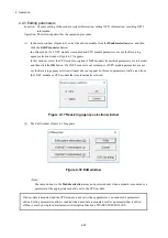
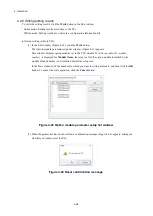
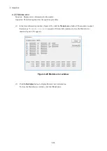
In online mode, if a J.NET module is mounted and CPU module parameters are set, the Receiving 

agency selection window (Figure 4-17) appears. 

In this window, select the CPU module or option (J.NET module) from which parameters are to be read, 

and then click the 

OK

 button. If a J.NET module is not mounted or if CPU module parameters are not 

set, the Receiving agency selection window does not appear. In this case, parameters will be read from 

the J.NET module or CPU module that is automatically selected. 


Figure 4-17 Receiving agency selection window 


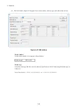
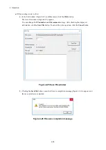
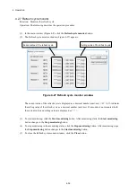
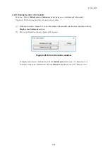
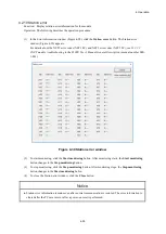
(2)  The Edit window (Figure 4-18) appears. 


Figure 4-18 Edit window 


<Note> 

The radio buttons in the 

Module selection

 area can be selected only when a module is mounted or a 

parameter of the appropriate module is set to the CPU module. 


If no module is mounted and the CPU module is not set with any parameter, you cannot edit parameters 

online. Editing parameters online is enabled when a module is mounted or after a parameter that is edited 

offline is sent by using the data transmission/reception function of BASE SYSTEM/S10VE. 

Summary of Contents for 510VE

Page 1: ...User s Manual Option J NET LQE540 E SEE 1 102 A ...

Page 2: ...User s Manual Option J NET LQE540 E ...

Page 3: ... clarification please contact your Hitachi sales representative Edition 1 October 2019 SEE 1 102 A No part of this material may be reproduced in any form or by any means without permission in writing from the publisher Information in this document is subject to change without notice For inquiries about this product please visit the following URL https www hitachi com s10 All Rights Reserved Copyri...

Page 4: ...injury and property damage or loss not related to personal injury used in the safety labels Serious injury Is an injury that has aftereffects and requires hospitalization for medical treatment or long term follow up care Examples of serious injuries are as follows vision loss burns caused by dry heat low temperature burns electric shock injuries broken bones and poisoning Minor or moderate injury ...

Page 5: ...ales staff The hazard warnings on the machine and in the manual cannot cover every possible case as it is impossible to predict and evaluate all circumstances You must be alert and use your common sense Do not perform any installation wiring handling or internal customization that is not described in this manual Hitachi will not be responsible for any damage to Hitachi equipment or peripherals and...

Page 6: ... maintenance area neat and tidy Make sure that maintenance parts materials and removed parts are not placed in a passageway so they are not tripped on by personnel Wear eye protection if there is a risk of flying debris When using sharp objects or cutting tools keep fingers and other parts of your body away from the path of the blade bit or point After maintenance work is completed before turning ...

Page 7: ...o ensure that the power is off Some parts in the machine remain charged for a certain time even after the power supply to the machine is disconnected Follow the displayed instructions When working on a machine which has a grounding terminal make sure that the terminal is properly connected to the facility s ground When working near an exposed live electric circuit do not work alone Work with anoth...

Page 8: ...nt by using a nonconductive object such as a dry wooden stick Call an ambulance If the victim is unconscious artificial respiration may be necessary A proper method for performing artificial respiration or resuscitation should be learned beforehand If the victim s heart is not beating cardio pulmonary resuscitation must be performed by a trained and qualified person In the case of fire Call the fi...

Page 9: ...Such settings might cause a malfunction See page 2 1 Poor contact might cause malfunction Mount the module and connect cabling to the module immediately after the module is unpacked so that dust or other foreign substances do not accumulate on connectors To avoid damaging a module when removing or mounting it turn off the power switch of the power supply module beforehand To avoid damaging a modul...

Page 10: ...ogram Files System root folder for example C Windows System drive root folder for example C Program data folder for example C ProgramData See page 4 2 J NET SYSTEM S10VE cannot be installed on a per user basis To install J NET SYSTEM S10VE successfully you must first log on to the system with an administrator account J NET SYSTEM S10VE might not be installed properly in any of the following cases ...

Page 11: ...umber configuration information that is edited offline cannot be sent by the data transmission reception function of BASE SYSTEM S10VE Setting 9999 as the PCs number enables transmission regardless of the PCs number of the S10VE However note that it becomes impossible to check transmission to unintended PCs See page 4 31 Station error information remains even after normal communication is restored...

Page 12: ... lift facility facility for recreation and amusement medical facility safety equipment on vehicle equipment ship facility traffic light system and other facilities where death or bodily harm might result in the event of an emergency Applications where a high level of responsibility is required Example Systems that supply gas water or electricity systems requiring round the clock operation system r...

Page 13: ...pair is limited to replacement of malfunctioning parts Work other than replacement of malfunctioning parts such as investigation into the cause of failure shall be charged even during the warranty period 2 Exception of warranty obligation Regardless of the warranty period Hitachi bears no responsibility in any of the following cases The warranty mentioned here means the warranty for the individual...

Page 14: ...ichever comes earlier The standard service life of S10VE is 10 years We cannot accept repair of products whose designated repair acceptance periods as described here have been exceeded Payment for any repair after expiration of the warranty is the responsibility of the customer 5 Service after production of the product is stopped Products including spare parts cannot be supplied after production o...

Page 15: ...S 12 Revision History Revision No History revision details Issue date Remarks A New edition Oct 2019 ...

Page 16: ...ations Memory capacities and requirements file sizes and storage requirements must be calculated according to the formula 2n The following examples show the results of such calculations by 2n to the right of the equal signs 1 KB kilobyte 1 024 bytes 1 MB megabyte 1 048 576 bytes 1 GB gigabyte 1 073 741 824 bytes 1 TB terabyte 1 099 511 627 776 bytes As for disk capacities they must be calculated u...

Page 17: ...g and Wiring 3 1 3 1 Mount base 3 1 3 2 Mounting the modules 3 1 3 3 External dimensions of the J NET module 3 3 3 4 Wiring 3 4 3 4 1 Interface signals and wiring method 3 4 3 4 2 Cable specifications 3 5 3 4 3 Wiring examples 3 6 4 Operation 4 1 4 1 Installing and starting up the system 4 1 4 1 1 Notes on installation 4 1 4 1 2 Installation 4 3 4 1 3 Uninstallation 4 6 4 1 4 Reinstallation 4 6 4 ...

Page 18: ...ror 4 35 4 2 11 CSV output 4 36 5 Programming 5 1 5 1 Software configuration of the J NET module 5 1 5 2 NET status 5 3 5 3 S register 5 4 5 4 S table 5 5 6 User s Guide 6 1 6 1 JEMA standard compliance 6 1 6 2 Communication times 6 1 7 Maintenance 7 1 7 1 Maintenance and inspection 7 1 7 2 Replacing or adding the module 7 1 7 3 Troubleshooting 7 1 8 Test and Maintenance Diagnosis 8 1 8 1 Details ...

Page 19: ...unication type window initial display 4 11 Figure 4 11 Open window 4 12 Figure 4 12 Select File window 4 13 Figure 4 13 Save As window 4 14 Figure 4 14 Creation confirmation window 4 15 Figure 4 15 Organization of J NET SYSTEM S10VE functions 4 17 Figure 4 16 Main window 4 18 Figure 4 17 Receiving agency selection window 4 20 Figure 4 18 Edit window 4 20 Figure 4 19 Edit system information window ...

Page 20: ...program 5 2 Figure 5 3 S register 5 4 Figure 6 1 Example of calculating communication time when J STATIONs are connected 6 2 Figure 8 1 Wiring required for external loopback check 8 2 Figure 8 2 Switch settings of the J NET module 8 4 Figure 8 3 TX and RX LEDs of the J NET module 8 5 Figure 8 4 ERR LEDs of the J NET module 8 6 ...

Page 21: ...Station timeout calculation formula for different communication speeds 4 25 Table 4 6 I O types 4 26 Table 4 7 List of transfer addresses that can be set 4 27 Table 5 1 I O areas 5 2 Table 5 2 NET status table configuration 5 3 Table 5 3 S table allocation main module 5 5 Table 5 4 S table allocation sub module 5 5 Table 5 5 S table allocation sub2 module 5 6 Table 5 6 S table allocation sub3 modu...

Page 22: ...ules 4 modules per CPU unit Weight 370 g or less Current consumption 900 mA or less Hot swapping Not supported 1 2 2 Communication specifications Table 1 2 Communication specifications Item Specifications Transmission method Serial bit serial transmission Electrical interface RS 485 Number of stations A maximum of 31 stations per network 62 stations per module Communication cable Line type Two pai...

Page 23: ...f vibration directions X Y and Z Sweep time 8 minutes number of sweep cycles 20 Shock resistance Peak acceleration 147 m s2 half sine shock time 11 ms applied direction of shock directions X Y and Z three times for each case Ambient air Dust 0 1mg m3 or less Corrosive gas JEITA IT 1004A Class B no corrosive gas must exist Notice To avoid damaging the product protect it with cushioning and then sto...

Page 24: ...he J NET module After the station has exchanged service information with the J NET module the data read service PUT request causes the station to write data to the J NET module GET command A station reads data from the J NET module After the J NET module has exchanged service information with a station the data read service GET request causes the station to read data from the J NET module Data wri...

Page 25: ...e of the J NET module you need the following hardware and software Personal computer PC with a CPU of 1 GHz or faster Display with a resolution of 1366 x 768 dots or higher FWXGA 2 GB or more RAM Free hard disk capacity of 200 MB or more Cable UTP crossed twisted pair cable of Category 5e or higher connected between PC and CPU module Microsoft Windows 7 64 bit operating system Microsoft Windows 10...

Page 26: ... Module 1 1 0 5 Mbps 2 Module 2 2 0 25 Mbps 3 Module 3 3 0 125 Mbps 4 to F Setting prohibited 4 to F Setting prohibited Table 2 3 Signal names and descriptions Signal name Description N1 N2 Network numbers TERM Terminal for a terminating resistor Short circuit the TERM and A terminals when the J NET module is used at the end of the network A B Terminal used to connect a transmission reception data...

Page 27: ...This page is intentionally left blank ...

Page 28: ...se applicable to the J NET module Name Model Specification 7 slot mount base HSC 1770 Power supply RI O IF CPU 7 I O slots 3 2 Mounting the modules Mount the option module in an I O slot slot No 1 to 7 on the mount base see Figure 3 1 Figure 3 1 Mounting the option module CPU module Option module I O slots Mount base Power supply module RI O IF module ...

Page 29: ...ff the power switch of the power supply module beforehand To avoid damaging a module observe the following precautions when mounting or removing the module Before mounting the module on the mount base connector check that the connector pins are properly aligned and not bent broken or soiled Connecting or disconnecting a module that is tilted might damage connector pins When moving the module hold ...

Page 30: ...rnal dimensions of the J NET module Figure 3 2 shows the external dimensions of the J NET module Figure 3 2 External dimensions of the J NET module 34 0 mm 21 5 mm or less 140 2 mm 130 0 mm TX RX ERR TX RX ERR TX RX TX RX LQE540 E J NET ...

Page 31: ...V 1 5 to 6 V Input condition 0 2 V or less 0 2 V or more Input condition refers to the electrical potential of A based on the input voltage of B Short circuit the TERM and A terminals when the J NET module is used at an end of the network The terminating resistor 120Ω is internally connected Notice Incorrect connection might cause malfunction Connect the frame ground FG terminal to the FG terminal...

Page 32: ... Recommended cable specifications Item Specifications Maximum conductor resistance 20 C 34 0Ω per km Withstand voltage 1000 VAC per minute Minimum insulation resistance 20 C 2500 MΩ km Capacitance 1 kHz 60 pF per m Characteristic impedance 1 MHz 110Ω Note The preceding table shows a characteristic impedance of 110Ω at 1 MHz However the J NET module has 120Ω internal terminating resistors in consid...

Page 33: ...works N1 and N2 each of which must be wired as a totally discrete network Figures 3 4 and 3 5 show wiring examples of N1 The same configuration applies for N2 Wiring for a J NET module that is at the end of the N1 line Figure 3 4 Network wiring example 1 S10VE CPU unit J NET module Terminated end Short circuit the TERM and A terminals JPCN 1 device Terminated end A B SHD SG TERM ...

Page 34: ...dule that is not at the end of the N1 line Figure 3 5 Network wiring example 2 Leave the TERM and A terminals open on a J NET module used between terminated ends J NET module S10VE CPU unit JPCN 1 device Terminated end Terminated end SHD TERM A B SG ...

Page 35: ...This page is intentionally left blank ...
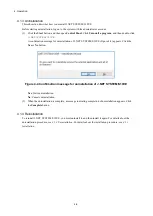
Page 36: ...ssing from your computer Try reinstalling the program to fix this problem Install the Microsoft Visual C 2010 redistributable package x64 in advance from the Microsoft download center Before you attempt to install J NET SYSTEM S10VE make sure that BASE SYSTEM S10VE software product model S 7898 38 has been installed If BASE SYSTEM S10VE has not been installed install it J NET SYSTEM S10VE cannot b...

Page 37: ...S10VE while any of these programs are running might cause an error If an error occurs uninstall the tool being installed terminate all Windows programs and then reinstall the tool For details about the uninstallation procedure see 4 1 3 Uninstallation Do not specify as the J NET SYSTEM S10VE installation folder any of the following folders protected by User Account Control Program file folder for ...

Page 38: ... To install J NET SYSTEM S10VE double click setup exe stored in the CD BASE SET S10VE 2 After double clicking SETUP exe the following message Figure 4 1 might be displayed Click the Yes button to start setup Figure 4 1 User Account Control message 3 In the SETUP window that appears Figure 4 2 select J NET SYSTEM S10VE and then click the Install button Figure 4 2 SETUP window ...

Page 39: ...lick the Yes or No button Yes Cancels installation of J NET SYSTEM S10VE In the InstallShield Wizard Completed window click the Complete button No Restarts installation of J NET SYSTEM S10VE 5 The Choose Destination Location window appears If necessary change the installation folder and then click the Next button 6 The Setup Status window appears 7 When the installation is complete the InstallShie...

Page 40: ... case log on with the administrator account that was first created on your computer and then reinstall J NET SYSTEM S10VE If you log on with a user account other than that used for installing J NET SYSTEM S10VE the installed program might not appear in the program menu In this case log off and log on again with the administrator account that was first created on your computer uninstall the install...

Page 41: ...NET SYSTEM S10VE Figure 4 4 appears Click the Yes or No button Figure 4 4 Confirmation message for uninstallation of J NET SYSTEM S10VE Yes Starts uninstallation No Cancels uninstallation 2 When the uninstallation is complete a message indicating completion of uninstallation appears Click the Complete button 4 1 4 Reinstallation To reinstall J NET SYSTEM S10VE you must uninstall it and then instal...

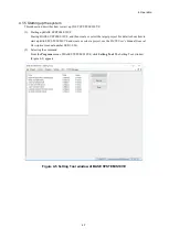
Page 42: ...n create or select the target project For details about how to start up BASE SYSTEM S10VE and create or select a project see the S10VE User s Manual General Description manual number SEE 1 001 2 Selecting the command From the Program menu of BASE SYSTEM S10VE click Setting Tool The Setting Tool window Figure 4 5 appears Figure 4 5 Setting Tool window of BASE SYSTEM S10VE ...

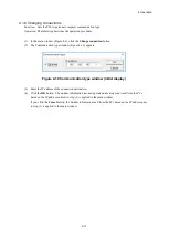
Page 43: ...dit a J NET module configuration information file without connecting to PCs see 5 Startup in offline state 4 Startup in online state a In the main window Figure 4 6 select the Online radio button and then click the Change connection button The Communication type window Figure 4 7 appears Specify the IP address of the connection destination and then click the OK button For details about how to sele...

Page 44: ...either mounted nor set are dimmed and cannot be selected Figure 4 8 Main window online status Select a valid module number and then click one of the following buttons Edit Parameter Use this button to read edit and reconfigure parameters set to the CPU module or J NET module For details see 4 2 3 Editing parameters Refresh cycle monitor Use this button to display and monitor the current refresh cy...

Page 45: ...EM S10VE a In the main window Figure 4 6 select the Offline radio button The Change connection button changes to the Edition file select button Figure 4 9 Main window Offline radio button selected Click one of the following buttons Edition file select Use this button to edit an existing configuration information file For details see 4 1 7 Selecting an edition file Create edition file Use this butt...

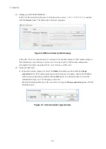
Page 46: ...n type window Figure 4 10 appears Figure 4 10 Communication type window initial display 3 Enter the IP address of the connection destination 4 Click the OK button The module information mounting state and setting state read from the PCs based on the IP address entered in step 3 is applied to the main window If you click the Cancel button the module information read from the PCs based on the IP add...

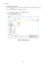
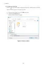
Page 47: ...ion information file to be edited This function works in the offline state Operation The following describes the operation procedure 1 In the main window Figure 4 6 select the Offline radio button 2 Click the Edition file select button The Open window Figure 4 11 appears Figure 4 11 Open window ...

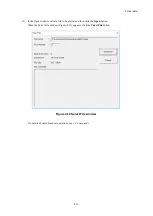
Page 48: ...n window select a file to be edited and then click the Open button When the Select File window Figure 4 12 appears click the Select File button Figure 4 12 Select File window For details about subsequent operations see 4 2 Commands ...

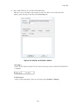
Page 49: ...uration information file This function works in the offline state Operation The following describes the operation procedure 1 In the main window Figure 4 6 select the Offline radio button 2 Click the Create edition file button The Save As window Figure 4 13 appears Figure 4 13 Save As window ...

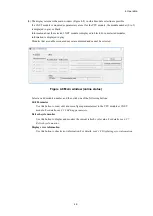
Page 50: ...odule module number enter a file comment and then click the Save File button Figure 4 14 Creation confirmation window PCs number Specify the PCs number By default the PCs number of the project selected by BASE SYSTEM S10VE is displayed Setting range 0 to 9999 Module selection Select a J NET module number Select one of the radio buttons Module 0 to Module 3 ...

Page 51: ...e comment You can enter any comment about the file by using a maximum of 512 characters For details about subsequent operations see 4 2 Commands 4 1 9 Closing the system In the main window Figure 4 6 click the Close button ...

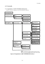
Page 52: ...n file selection Indicates that the functions enclosed can be used only when J NET SYSTEM S10VE is running in online mode Parameter editing NET1 refresh cycle setting NET2 refresh cycle setting NET1 status table address setting NET2 status table address setting ID selection Station number setting Station type setting Refresh cycle setting Input output area setting Slot setting Transfer area settin...

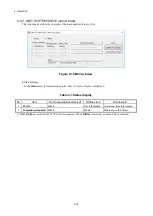
Page 53: ...tus area information shown in Table 4 1 Status display is displayed Table 4 1 Status display No Item Not connected not selected Offline state Online state 1 PCsNo Blank File information Actual machine information 2 Communication kind Blank Blank Ethernet and IP address When Online is selected the S10VE is not connected When Offline is selected no edition file is selected ...

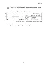
Page 54: ...e parameters set Mounting state display Setting state display Receiving source 1 Yes Yes Mounting Setting Selected from the Receiving agency selection dialog box 2 No Not setting J NET module 3 No Yes Non mounting Setting CPU module 4 Not Not setting Reception not possible Receiving agency indicates the module from which parameters to be edited are read Mounting status and Setting status display o...

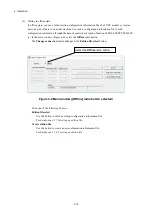
Page 55: ...tton If a J NET module is not mounted or if CPU module parameters are not set the Receiving agency selection window does not appear In this case parameters will be read from the J NET module or CPU module that is automatically selected Figure 4 17 Receiving agency selection window 2 The Edit window Figure 4 18 appears Figure 4 18 Edit window Note The radio buttons in the Module selection area can ...

Page 56: ...ation shorter than the communication time calculated in section 6 2 Setting range 3 to 3000 Unit ms Setting the NET1 NET2 status table Set the starting address of the NET status table Set the address listed in Table 4 3 NET status table addresses that can be set by using the PI O register format Table 4 3 NET status table addresses that can be set No Address that can be set PI O register setting r...

Page 57: ...4 Operation 4 22 3 When the setting is complete click the OK button To cancel the setting click the Cancel button ...

Page 58: ...Operation The following describes the operation procedure 1 In the Edit window Figure 4 18 click the Edit NET1 information or Edit NET2 information button 2 The Edit information window Figure 4 20 appears Click the ID station ID to be edited and then click the Edit button Setting range H01 to H1F Figure 4 20 Edit information window ...

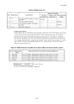
Page 59: ...ime Figure 4 21 Edit window Station number Set the station number to be assigned to the substation Setting range H01 to H7F Station type Select the station type that best suits the substation specifications Select from among the station types in Table 4 4 Note Do not select J STATION EXTENDED or J STATION STANDARD ...

Page 60: ...or example power failure or disconnection the refresh cycle of the J NET module is prolonged This might cause a communication error in another substation that is communicating normally To prevent this communication error set the value calculated by using the formula indicated in Table 4 5 Station timeout calculation formula for different communication speeds Table 4 5 Station timeout calculation f...

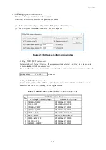
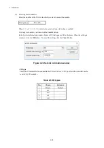
Page 61: ... click the Set slot button In the Set slot information window Figure 4 22 that appears fill in the items When the setting is complete click the OK button To cancel the setting click the Cancel button Figure 4 22 Set slot information window I O type Select the I O module to be mounted in the I O slot Table 4 6 I O types lists the items that can be selected for I O modules Table 4 6 I O types No Cho...

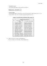
Page 62: ...register setting range Address setting range 1 XW0000 to XWFFF0 H441000 to H442FFE 2 JW000 to JWFF0 H0E0200 to H0E03FE 3 YW0000 to YWFFF0 H443000 to H444FFE 4 QW0000 to QWFFF0 H445000 to H446FFE 5 GW000 to GWFF0 H0E0800 to H0E09FE 6 RW000 to RWFF0 H0E0C00 to H0E0DFE 7 MW0000 to MWFFF0 H447000 to H448FFE 8 EW0400 to EWFFF0 H449080 to H44AFFE 9 FW000 to FWBFF H0E2000 to H0E37FE 10 LBW0000 to LBWFFF0...

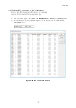
Page 63: ...ndow displays option modules set in the CPU module If NONE module ID module number is displayed for Module Name the setup tool for the option module identified by the module ID and number is not installed Install the setup tool In the No column click the number for which you want to write parameters and then click the OK button To cancel the write operation click the Cancel button Figure 4 23 Opti...

Page 64: ...tion by using the written parameters If reset of the PCs fails the message PCs reset failed appears In this case manually reset the PCs or perform a power on reset For details about how to manually reset the PCs see 8 4 3 5 Online menu Remote reset in the S10VE User s Manual General Description manual number SEE 1 001 Notice Until the PCs are reset the parameters written to the CPU modules do not ...

Page 65: ... change the PCs number and File comment settings After checking the displayed information click the Save File button To cancel the write operation click the Cancel button Figure 4 25 Save File window 2 Clicking the Save File button causes the file save completion message Figure 4 26 to appear and the save operation is completed Figure 4 26 File save completion message ...

Page 66: ...Cs number configuration information that is edited offline cannot be sent by the data transmission reception function of BASE SYSTEM S10VE Setting 9999 as the PCs number enables transmission regardless of the PCs number of the S10VE However note that it becomes impossible to check transmission to unintended PCs ...

Page 67: ...s the setting value of the refresh cycle as a decimal number unit ms If a module is not mounted both the current value and setting value are displayed as 3 To start monitoring click the Start monitoring button After monitoring starts the Start monitoring button changes to the Stop monitoring button 4 To stop monitoring in the monitoring status click the Stop monitoring button After monitoring stop...

Page 68: ... 1 In the main window Figure 4 8 select the module in the module selection area and then click the Display error information button 2 The Error information window Figure 4 28 appears Figure 4 28 Error information window To display module error information click the Module error button see 4 2 9 Module error To display station error information click the Station error button see 4 2 10 Station erro...

Page 69: ...r information window Figure 4 28 click the Module error button If the module is normal the message The module is normal appears If the module contains an error the Module error window Figure 4 29 appears Figure 4 29 Module error window 2 Click the Redisplay button to display the latest error information To close the Module error window click the Close button ...

Page 70: ...s Manual General Description manual number SEE 1 001 Figure 4 30 Station error window 2 To start monitoring click the Start monitoring button After monitoring starts the Start monitoring button changes to the Stop monitoring button 3 To stop monitoring click the Stop monitoring button After monitoring stops the Stop monitoring button changes to the Start monitoring button 4 To close the Station er...

Page 71: ...nline mode establish a connection between the J NET system and the PCs see 4 1 6 Changing connections In offline mode select an edition file see 4 1 7 Selecting an edition file 2 In the main window Figure 4 8 click the Edit Parameter button The Edit window appears see 4 2 3 Editing parameters 3 In the Edit window Figure 4 18 click the CSV Output button 4 The Save As window Figure 4 31 appears Spec...

Page 72: ...H04 FW100 H04 FW200 VALID H06 H06 J STATION EXT 000200 ID H01 Slot information Slot number I O type Transfer bytes Transfer address H0 DI H04 FW100 H1 DO H04 FW200 H2 H3 H4 H5 H6 H7 H8 H9 HA HB HC HD HE HF NET2 information System information Refresh cycle Sequence cycle Status table address Unused Station information ID Station number Station type Station timeout time Input byte Input address Outp...

Page 73: ...This page is intentionally left blank ...
Page 74: ...oes not need to be loaded Figure 5 1 Software configuration of the J NET module Communication control program ROM program Table or buffer ROM CPU module NET status S register Send area Receive area I O area Communication control circuit S table Send buffer Receive buffer I O buffer Slave parameter table J NET module Cable Station PI O module Communication control circuit Communication control circ...

Page 75: ... I O areas Name Symbol range Number of points External input XW0000 X0000 to XWFFF0 XFFFF 4 096 words 65 536 points External output YW0000 Y0000 to YWFFF0 YFFFF 4 096 words 65 536 points Internal register RW000 R000 to RWFF0 RFFF 256 words 4 096 points Global link register GW000 G000 to GWFF0 GFFF 256 words 4 096 points Transfer register JW000 J000 to JWFF0 JFFF 256 words 4 096 points Receive regi...

Page 76: ...to EFFFF M0000 to MFFFF LB0000 to LBFFFF A NET status table with a capacity of 128 consecutive points needs to be registered for N1 and N2 respectively For example if a NET status table starting at X0500 is specified it would take up X0500 to X057F In this case X05 is displayed in in Table 5 2 Table 5 2 NET status table configuration denotes a registered symbol Station ID Send enable flag Data rec...

Page 77: ... S0A 1 0 NET1 is running normally 1 A hardware error occurred in NET1 S0A 8 0 Communication over NET2 is proceeding normally 1 A communication error occurred in NET2 S0A 9 0 NET2 is running normally 1 A hardware error occurred in NET2 Note Other bits cannot be used Figure 5 3 S register 215 28 27 20 SW0A 0 S0A 0 S0A 1 S0A 2 S0A 3 S0A 4 S0A 5 S0A 6 S0A 7 S0A 8 S0A 9 S0A A S0A B S0A C S0A D S0A E S0...

Page 78: ...Error code N1 255 A40000 A40040 A40080 1 A40002 A40042 A40082 2 A40004 A40044 A40084 30 A4003C A4007C A400BC 31 A4003E A4007E A400BE N2 255 A40100 A40140 A40180 1 A40102 A40142 A40182 2 A40104 A40144 A40184 30 A4013C A4017C A401BC 31 A4013E A4017E A401BE Table 5 4 S table allocation sub module Network number Station ID Sub module Number of bytes in received data Number of bytes in received respons...

Page 79: ...0 C40140 C40180 1 C40102 C40142 C40182 2 C40104 C40144 C40184 30 C4013C C4017C C401BC 31 C4013E C4017E C401BE Table 5 6 S table allocation sub3 module Network number Station ID Sub3 module Number of bytes in received data Number of bytes in received responses Error codes N1 255 CC0000 CC0040 CC0080 1 CC0002 CC0042 CC0082 2 CC0004 CC0044 CC0084 30 CC003C CC007C CC00BC 31 CC003E CC007E CC00BE N2 255...

Page 80: ...a J NET module The communication time of a J NET module is the sum of each slave device s communication time indicated in the following formula In other words if slave devices connected to the J NET module are assumed as slave device 1 slave device 2 slave device n the communication time is calculated as follows Communication time Communication time of slave device 1 Communication time of slave de...

Page 81: ...ication time is 11 1 ms Figure 6 1 Example of calculating communication time when J STATIONs are connected Communication time J STATION 1 communication time J STATION 2 communication time J STATION 3 communication time 1 85 0 0031 x 128 128 1 85 0 0031 x 256 256 1 85 0 0031 x 512 512 2 64 3 44 5 02 11 1 ms Transmission speed 1 Mbps Input 128 points Output 128 points J NET Input 256 points Output 2...

Page 82: ...mounting screws and communication cable mounting screws for looseness and damage Tighten any loose screws and replace any damaged ones At least twice a year 7 2 Replacing or adding the module For details about how to replace or add the J NET module see Chapter 14 Replacing or Adding Modules in the S10VE User s Manual General Description manual number SEE 1 001 7 3 Troubleshooting As a guide for tr...

Page 83: ...This page is intentionally left blank ...
Page 84: ...between NET1 and NET2 internally to confirm that data can be transmitted and received normally No 2 T M2 Internal memory compare check Use long word word and byte accordingly as the unit to compare with the internal memory of the J NET module and check for consistency No 3 T M3 CPU memory compare check From the J NET module use word as the unit to compare with the internal memory of the CPU module...

Page 85: ...igure 8 1 shows the wiring required for external loopback check Figure 8 1 Wiring required for external loopback check LQE540 E J NET A B Connect the A terminal of N1 NET1 to that of N2 NET2 then the B terminal of N1 NET1 to that of N2 NET2 There is no need to connect the SG and SHD terminals to each other ...

Page 86: ...rm wiring as shown in 8 2 Wiring method 2 Select the test item and module type by using the MODU No and BIT RATE setting switches of the J NET module Table 8 2 shows the correlation between test items module types and switch settings of the CPU module required to start Test and Maintenance Table 8 2 Test item and module type selected by the setting switches Switch settings of the J NET module Test...

Page 87: ... and RX LED are either on or blinking Table 8 3 shows the LED states during the Test and Maintenance operation Table 8 3 LED states during the Test and Maintenance operation Test item N1 NET1 N2 NET2 TX LED RX LED ERR LED TX LED RX LED ERR LED T M1 On On On On T M2 Off Blinking Off Blinking T M3 Off On Off On T M4 On On On On The ERR LED N1 and N2 turns on only when an error occurs For details see...

Page 88: ...top the Test and Maintenance operation turn off the power switch of the power supply module 6 To return to normal operation reset the switches to their states before performing Test and Maintenance and then restore backup data N1 NET1 TX and RX LEDs N2 NET2 TX and RX LEDs LQE540 E J NET A B ...

Page 89: ...8 4 To check more details connect the tool to the CPU unit and then check the address indicated in Table 8 5 For details about the tool see the S10VE User s Manual General Description manual number SEE 1 001 Figure 8 4 ERR LEDs of the J NET module Table 8 4 Location of problem for lighting ERR LED and corrective actions Test item Possible problem location Corrective action T M1 and T M2 J NET modu...

Page 90: ...6 NET2 transmission error status T M1 or T M4 00A40E48 00AC0E48 NET1 reception error status T M1 or T M4 00A40E4A 00AC0E4A NET2 reception error status T M1 or T M4 00A40E4C 00AC0E4C Long word access check error count in internal RAM T M2 00A40E50 00AC0E50 Word access check error count in internal RAM T M2 00A40E54 00AC0E54 Byte access check error count in internal RAM T M2 00A40E58 00AC0E58 Long w...

Page 91: ...This page is intentionally left blank ...
Reviews: