

3. Mounting and Wiring
3-4
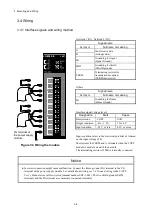
3.4 Wiring
3.4.1 Interface signals and wiring method
Network 1 (N1), Network 2 (N2)
Signal name
Acronym
Full name or meaning
A
Send/receive data
(Linkage data)
B
SG
Grounding for signal
(Signal Ground)
SHD
Grounding for shield
(SHielD ground)
TERM
Terminating resistor for
transmission/reception
(TERMinal resistor)
Others
Signal name
Acronym
Full name or meaning
FG
Grounding for frame
(Frame Ground)
Interface signal voltage levels
Designation
Mark
Space
Interpretation
1/OFF
0/ON
Output condition
-6 to -1. 5 V
1.5 to 6 V
Input condition
-0.2 V or less
0.2 V or more
Input condition refers to the electrical potential of A based
on the input voltage of B.
Short-circuit the TERM and A terminals when the J.NET
module is used at an end of the network.
The terminating resistor (120Ω) is internally connected.
Notice
●
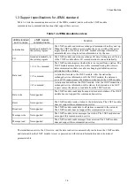
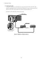
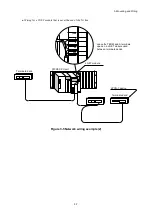
Incorrect connection might cause malfunction. Connect the frame ground (FG) terminal to the FG
terminal of the power supply module. For details about wiring, see
7.4 Ground wiring
in the
S10VE
User's Manual General Description
(manual number SEE-1-001). The two shield ground (SHD)
terminals and the FG terminal are commonly connected internally.
Figure 3-3 Wiring the module
FG terminal of
the power supply
module
LQE540-E
J.NET
A
B
Summary of Contents for 510VE
Page 1: ...User s Manual Option J NET LQE540 E SEE 1 102 A ...
Page 2: ...User s Manual Option J NET LQE540 E ...
Page 27: ...This page is intentionally left blank ...
Page 35: ...This page is intentionally left blank ...
Page 73: ...This page is intentionally left blank ...