


47
DP33KA/B
1
,
2
≤±
2mm
1
≤
±2 mm
Notes: (1) If internal cross-hatch does not appear after
clearing RAM data, press service switch
again, on DEF./CONV. PWB.
(2) To restore old RAM data, turn TV off and on.
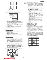
CROSSHATCH (GREEN)
2
(4) Receive cross-hatch signal.
Adjustment procedure
(1) Green (G) tube beam alignment adjustment.
Short-circuit 2P subminiature connector plug
pins of Red (R) and Blue (B) on the CPT boards
and project only Green (G) light or you may
cover the R and B lens.
(2) Put Green (G) tube beam alignment magnet to
the cancel state as shown below.
(3) Turn the Green (G) static focus (Focus Pack)
counterclockwise all the way and make sure of
position of cross-hatch center on screen. (Halo
state.)
(4) Turn the Green (G) static focus (Focus Pack)
clockwise all the way. (Blooming state.)
(5) Turn two magnets forming alignment magnet in
any desired direction and move cross-hatch
center to position found in (3).
(6) If image position does not shift when Green (G)
static focus (Focus Pack) is turned. Green (G)
beam alignment has been completed.
(7) If image position shifts when Green (G) static
focus (Focus Pack) is turned, repeat (2)-(6).
(8) Conduct beam alignment for red (R) and
Blue (B) focus: Focus Pack UFPK.
(9) Upon completion of adjustment, fix beam
alignment magnets with white paint.
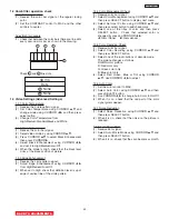
2.5 Beam alignment
Adjustment preparation
(1) Adjust at least 30 minutes after turning on power
switch.
(2) Raster tilt should be completed. Raster position,
horizontal and vertical size, and optical focus
adjustment should be coarse adjusted.
(3) Set video conditions to factory preset.
(4) Turn the deflection yoke of R or B and set so that the
inclination of R or B light with respect to the green
light is as shown below on the top and bottom sides.
(5) After raster inclination adjustment, fixing screw of DY
should be screwed with 12±2kg-cm torque.
Circle center
DCU crosshatch center
DCU crosshatch
Circle pattern
BACK TO ADJUSTMENTS
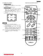
2.3 Horiontal Position Adjustment (Coarse)
Adjustment preparation
(1) DCU PHASE DATA SETTING should be
finished.
Adjustment procedure
(1) Receive circle pattern.
(2) Push SERVICE ONLY switch to display DCU
crosshatch. Mark the DCU crosshatch center
position using your finger tip.
(3) Push SERVICE ONLY switch again to exit from
the DCU crosshatch.
(4) Go to I
2
C ADJ. mode.
(5) Choose H. POSI item by using R/C MENU (or
up/down cursor) key. Adjust horizontal position
to match the circle center to DCU crosshatch
center (marked by your finger tip).
(6) Exit from I
2
C menu.
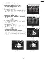
1080i 16:9 STANDARD MODE
(7) Receive any 1080i Signal (fH=33.75KHz) circle
pattern signal (Input to component video
terminal).
(8) Repeat steps (2)~(5).
(9) Press SELECT key, then H. POS H will appear.
It means HD mode is activated.
(10) Exit from I
2
C menu.
2.4 Raster Tilt adjustment (Deflection yoke)
Adjustment preparation
(1) The set can face east or west.
(2) Input the single cross test signal.
(3) Set CONTRAST to MAX, other controls to
CENTER.
(4) The lens focus and horizontal position
adjustment should have been coarse adjusted.
(5) The static focus should have been coarse
adjusted.
(6) The digital convergence RAM should be cleared
(uncorrected state). With the TV set off, press
and hold the “SERVICE ONLY” switch located on
the DEF./CONV. PWB and then press the power
button.
(7) Start adjustment 20 minutes or more after TV is
turned on.
Adjustment procedure
(1) Short-circuit 2P (TS) sub-mini connectors on
Red and Blue CPT P.W.B.s to project only the
Green beam.
(2) Turn the G deflection yoke and adjust the vertical
raster inclination.
(3) Then, remove the shorted wire on the 2P(TS)
sub-mini connectors on the R or B CPT PWB
and project red or blue light and green light
together on screen.
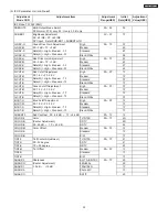
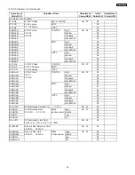
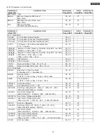
Summary of Contents for 46F500A
Page 28: ...28 DP33KA B a Adjust Mode OSD continued ...
Page 29: ...29 DP33KA B a Adjust Mode OSD continued ...
Page 30: ...30 DP33KA B a Adjust Mode OSD continued ...
Page 56: ...56 DP33KA B Convergence For Outside Signal function ...
Page 111: ...PRINTED CIRCUIT BOARD SIGNAL P W B PART SIDE 111 DP33KA B TABLE OF CONTENTS ...
Page 112: ...DP33KA B PRINTED CIRCUIT BOARD SIGNAL P W B PATTERN SIDE 112 ...
Page 113: ...PRINTED CIRCUIT BOARD TERMINAL P W B PART SIDE 113 DP33KA B ...
Page 114: ...PRINTED CIRCUIT BOARD TERMINAL P W B PATTERN SIDE 114 DP33KA B ...
Page 115: ...DP33KA B PRINTED CIRCUIT BOARD POWER P W B PART SIDE 115 ...
Page 116: ...PRINTED CIRCUIT BOARD POWER P W B PATTERN SIDE 116 DP33KA B ...
Page 117: ...DP33KA B PRINTED CIRCUIT BOARD DEFLECTION P W B PART SIDE 117 ...
Page 118: ...PRINTED CIRCUIT BOARD DEFLECTION P W B PATTERN SIDE 118 DP33KA B ...
Page 119: ...DP33KA B PRINTED CIRCUIT BOARD CPT P W B PART SIDE 46F500A 119 ...
Page 120: ...PRINTED CIRCUIT BOARD CPT P W B PATTERN SIDE 120 DP33KA B ...
Page 121: ...PRINTED CIRCUIT BOARD 46F510 CONTROL P W B 121 DP33KA B ...
Page 122: ...DP33KA B PRINTED CIRCUIT BOARD DVI P W B PART SIDE 122 ...
Page 123: ...PRINTED CIRCUIT BOARD DVI P W B PATTERN SIDE 123 DP33KA B ...
Page 124: ...BLOCK DIAGRAM 124 DP33KA B TABLE OF CONTENTS ...
Page 125: ...125 DP33KA B WIRING DIAGRAM TABLE OF CONTENTS ...
Page 162: ......


