14
DP33KA/B
GENERAL INFORMATION
46F510
TABLE OF CONTENTS
INPUT 5
S-VIDEO VIDEO
AUDIO
L/MONO
R
EXIT
INPUT
SELECT
MENU
VOL-
VOL+
CH-
CH+
E
F
G
H
c
f
a
b
d
g
e
CURSOR
MAGIC
FOCUS
e
h
a
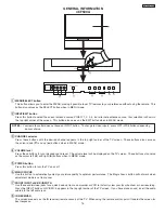
MENU/SELECT button
This button allows you to enter the MENU, making it possible to set TV features to your preference without using the remote. This
button also serves as the SELECT button when in MENU mode.
b
INPUT/EXIT button
Press this button to select the current antenna source, VIDEO: 1, 2, 3, 4, 5 or alternate antenna source. Your selection is shown in
the top right corner of the screen. This button also serves as the EXIT button when in MENU mode.
c
CHANNEL selector
Press these buttons until the desired channel appears in the top right corner of the TV screen. These buttons also serve as
the cursor down (
H
) and up (
G
) buttons when in MENU mode.
d
VOLUME level
Press these buttons for your desired sound level. The volume level will be displayed on the TV screen. These buttons also serve
as the cursor left (
F
) and right (
E
) buttons when in MENU mode.
e
POWER button/POWER LED
Press this button to turn the TV on or off. This LED light is ON during normal operation.
f
MAGIC FOCUS
Use this button to automatically adjust your picture quality to optimum performance. The Magic Focus button will not work when
adjustment mode is set to manual.
g
FRONT INPUT JACKS (INPUT 5)
Use these audio/video jacks for a quick hook-up from a camcorder or VCR to instantly view your favorite show or new recording.
Press the INPUT button until VIDEO: 5 appears in the top right corner of the TV screen. If you have mono sound, insert the audio
cable into the left audio jack.
h
IR RECEIVER Sensor
When using the remote control, point it towards the IR receiver for best response.
NOTES: Your remote control does not have an INPUT button. To change to video inputs, press VID1~VID5 buttons depending
on your choice.
Summary of Contents for 46F500A
Page 28: ...28 DP33KA B a Adjust Mode OSD continued ...
Page 29: ...29 DP33KA B a Adjust Mode OSD continued ...
Page 30: ...30 DP33KA B a Adjust Mode OSD continued ...
Page 56: ...56 DP33KA B Convergence For Outside Signal function ...
Page 111: ...PRINTED CIRCUIT BOARD SIGNAL P W B PART SIDE 111 DP33KA B TABLE OF CONTENTS ...
Page 112: ...DP33KA B PRINTED CIRCUIT BOARD SIGNAL P W B PATTERN SIDE 112 ...
Page 113: ...PRINTED CIRCUIT BOARD TERMINAL P W B PART SIDE 113 DP33KA B ...
Page 114: ...PRINTED CIRCUIT BOARD TERMINAL P W B PATTERN SIDE 114 DP33KA B ...
Page 115: ...DP33KA B PRINTED CIRCUIT BOARD POWER P W B PART SIDE 115 ...
Page 116: ...PRINTED CIRCUIT BOARD POWER P W B PATTERN SIDE 116 DP33KA B ...
Page 117: ...DP33KA B PRINTED CIRCUIT BOARD DEFLECTION P W B PART SIDE 117 ...
Page 118: ...PRINTED CIRCUIT BOARD DEFLECTION P W B PATTERN SIDE 118 DP33KA B ...
Page 119: ...DP33KA B PRINTED CIRCUIT BOARD CPT P W B PART SIDE 46F500A 119 ...
Page 120: ...PRINTED CIRCUIT BOARD CPT P W B PATTERN SIDE 120 DP33KA B ...
Page 121: ...PRINTED CIRCUIT BOARD 46F510 CONTROL P W B 121 DP33KA B ...
Page 122: ...DP33KA B PRINTED CIRCUIT BOARD DVI P W B PART SIDE 122 ...
Page 123: ...PRINTED CIRCUIT BOARD DVI P W B PATTERN SIDE 123 DP33KA B ...
Page 124: ...BLOCK DIAGRAM 124 DP33KA B TABLE OF CONTENTS ...
Page 125: ...125 DP33KA B WIRING DIAGRAM TABLE OF CONTENTS ...
Page 162: ......


