45
DP33KA/B
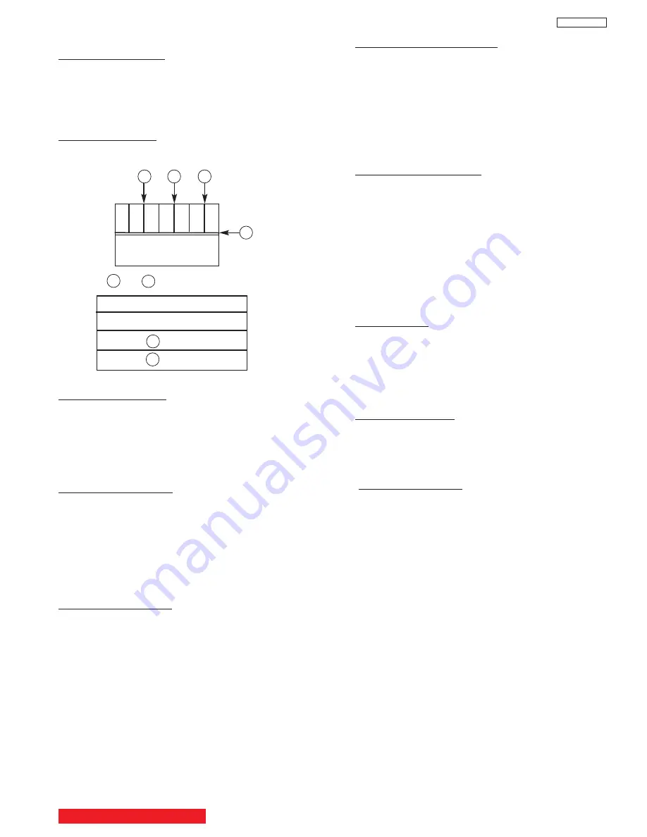
1.2 Comb filter operation check
Adjustment preparation
(1) Receive the color bar signal at the regular tuning
point.
(2) Set the CONTRAST control to MAX and the other
controls to center.
Adjustment procedure
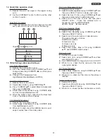
(1) Check that between the color bars there are line dots
every second color bar as shown in the drawing.
A
A
A
B
3D Y/C
Dots
A None
B None
Check and line dots.
B
A
1.3 Video Settings (Advanced Settings)
1.3.1 Color Temperature
(1) Receive the Circle pattern signal.
(2) Set Color Temperature using
CURSOR
G
,
H
and
change mode using
CURSOR
F
,
E
and then press
select button.
(3) Change Color Temperature from
High/Medium/Standard/Black and White.
1.3.2 Black Enhancement
(1) Receive the color bar signal.
(2) Select video mode by using
CURSOR
G
,
H
.
(3) Press
CURSOR
G
,
H
to select Black Enhancement
then press
CURSOR
E
.
(4) Select Black Enhancement using
CURSOR
F
,
E
and set it to High/Medium/Low/Off.
(5) When the mode is High, check that the black level
sinks at the black position of picture.
1.3.3 Edge Enhancement
(1) Receive the circle pattern signal.
(2) Adjust Edge Enhancement using
CURSOR
F
,
E
from High/Medium/Low/Off.
(3) When set to High, check that definition level is up at
edge of vertical line of the circle pattern.
1.3.4 Color Management Check
(1) Receive color bar signal.
(2) Select Color Management using
CURSOR
G
,
H
and
then press SELECT button to display next menu.
(3) Select Set User Colors using
CURSOR
G
,
H
and
then press select button to add check-mark.
(4) Select one of the titles of color and then press
SELECT button.
Check that selected color is
changed by pressing
CURSOR
F
,
E
.
F
: Gets thinner
E
: Gets denser
1.3.5 Color Decoding Check
(1) Receive color bar signal.
(2) Select Color Decoding using
CURSOR
G
,
H
and
then press SELECT button.
(3) Select one of the radio buttons of decode mode.
The picture changes as follows:
RGB: Normal picture
R: Red color only
G: Green color only
B: Blue color only
(4) Select Red, Green, Blue or Tint using
CURSOR
G
,
H
. Use
CURSOR
F
,
E
to adjust.
1.3.6 Auto Color
(1) Set the color control to MAX.
(2) Select Auto Color using
CURSOR
G
,
H
and then
press SELECT button.
(3) Use
CURSOR
F
,
E
to change Auto Color to On/Off.
(4) When it is on, check that the red part of the color
signal grows deeper.
1.3.7 Noise Reduction
(1) Select Noise Reduction using
CURSOR
G
,
H
and
then press SELECT button.
(2) When it is on, check that the noise on the picture is
reduced.
1.3.8 Auto Movie Mode
(1) Receive 480i signal.
(2) Select Auto Movie Mode using
CURSOR
G
,
H
and
then press SELECT button.
(3) When it is on, check that the scan becomes smooth.
BACK TO ADJUSTMENTS
Summary of Contents for 46F500A
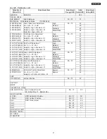
Page 28: ...28 DP33KA B a Adjust Mode OSD continued ...
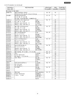
Page 29: ...29 DP33KA B a Adjust Mode OSD continued ...
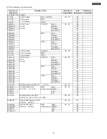
Page 30: ...30 DP33KA B a Adjust Mode OSD continued ...
Page 56: ...56 DP33KA B Convergence For Outside Signal function ...
Page 111: ...PRINTED CIRCUIT BOARD SIGNAL P W B PART SIDE 111 DP33KA B TABLE OF CONTENTS ...
Page 112: ...DP33KA B PRINTED CIRCUIT BOARD SIGNAL P W B PATTERN SIDE 112 ...
Page 113: ...PRINTED CIRCUIT BOARD TERMINAL P W B PART SIDE 113 DP33KA B ...
Page 114: ...PRINTED CIRCUIT BOARD TERMINAL P W B PATTERN SIDE 114 DP33KA B ...
Page 115: ...DP33KA B PRINTED CIRCUIT BOARD POWER P W B PART SIDE 115 ...
Page 116: ...PRINTED CIRCUIT BOARD POWER P W B PATTERN SIDE 116 DP33KA B ...
Page 117: ...DP33KA B PRINTED CIRCUIT BOARD DEFLECTION P W B PART SIDE 117 ...
Page 118: ...PRINTED CIRCUIT BOARD DEFLECTION P W B PATTERN SIDE 118 DP33KA B ...
Page 119: ...DP33KA B PRINTED CIRCUIT BOARD CPT P W B PART SIDE 46F500A 119 ...
Page 120: ...PRINTED CIRCUIT BOARD CPT P W B PATTERN SIDE 120 DP33KA B ...
Page 121: ...PRINTED CIRCUIT BOARD 46F510 CONTROL P W B 121 DP33KA B ...
Page 122: ...DP33KA B PRINTED CIRCUIT BOARD DVI P W B PART SIDE 122 ...
Page 123: ...PRINTED CIRCUIT BOARD DVI P W B PATTERN SIDE 123 DP33KA B ...
Page 124: ...BLOCK DIAGRAM 124 DP33KA B TABLE OF CONTENTS ...
Page 125: ...125 DP33KA B WIRING DIAGRAM TABLE OF CONTENTS ...
Page 162: ......

