


4
42PD7200 (PW2)
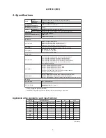
3. Service points
Lead free solder
This product uses lead free solder (unleaded) to help preserve the environment. Please read these instructions
before attempting any soldering work.
Caution:
Always wear safety glasses to prevent fumes or molten solder from getting into the eyes. Lead free
solder can splatter at high temperatures (600˚C).
Lead free solder indicator
Printed circuit boards using lead free solder are engraved with an "F."
Properties of lead free solder
The melting point of lead free solder is 40-50˚C higher than leaded solder.
Servicing solder
Solder with an alloy composition of Sn-3.0Ag-0.5Cu or Sn-0.7Cu is recommended.
Although servicing with leaded solder is possible, there are a few precautions that have to be taken. (Not taking
these precautions may cause the solder to not harden properly, and lead to consequent malfunctions.)
Precautions when using leaded solder
Remove all lead free solder from soldered joints when replacing components.
If leaded solder should be added to existing lead free joints, mix in the leaded solder thoroughly after the lead
free solder has been completely melted (do not apply the soldering iron without solder).
Servicing soldering iron
A soldering iron with a temperature setting capability (temperature control function) is recommended.
The melting point of lead free solder is higher than leaded solder. Use a soldering iron that maintains a high
stable temperature (large heat capacity), and that allows temperature adjustment according to the part being
serviced, to avoid poor servicing performance.
Recommended soldering iron:
Soldering iron with temperature control function (temperature range: 320-450˚C)
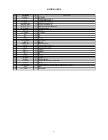
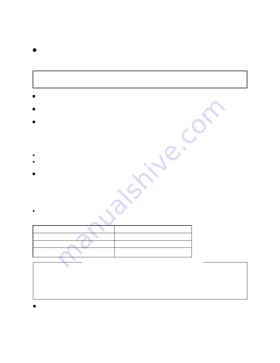
Recommended temperature range per part:
Part
Soldering iron temperature
Mounting (chips) on mounted PCB
320˚C±30˚C
Mounting (chips) on empty PCB
380˚C±30˚C
Chassis, metallic shield, etc.
420˚C±30˚C
FILTER PWB, SW PWB, LED/RECEIVER PWB, SP TERMINAL(L/R) PWB
AUDIO PWB, JOINT PWB, Swievel PWB, HDMI PWB, control PWB
VIDEO PWB
TUNER PWB
The PWB assembly which has used lead free solder
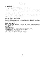
Readjustment Power supply voltage
When a PANEL or a Power Unit is exchanged, power supply voltage needs to be adjusted. Please adjust to
make the values of Va and Vs of as should on the label currently stuck on the panel back upper parts.Adjust-
ment is performed by VR in the power supply unit. Please refer to the procedures of “Va” and “Vs” adjustments
on 23page.
Summary of Contents for 42PD7200
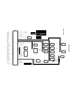
Page 10: ...9 42PD7200 PW2 Block diagram ...
Page 41: ...40 42PD7200 PW2 MEMO ...
Page 42: ...41 42PD7200 PW2 9 Basic circuit diagram 1 2 3 4 5 6 6 1 2 3 4 5 D A B C E F G ...
Page 43: ...42 42PD7200 PW2 1 2 3 4 5 6 6 1 2 3 4 5 D A B C E F G ...
Page 44: ...43 42PD7200 PW2 1 2 3 4 5 6 6 1 2 3 4 5 D A B C E F G ...
Page 45: ...44 42PD7200 PW2 1 2 3 4 5 6 6 1 2 3 4 5 D A B C E F G ...
Page 46: ...45 42PD7200 PW2 1 2 3 4 5 6 6 1 2 3 4 5 D A B C E F G ...
Page 47: ...46 42PD7200 PW2 1 2 3 4 5 6 6 1 2 3 4 5 D A B C E F G ...
Page 48: ...47 42PD7200 PW2 1 2 3 4 5 6 6 1 2 3 4 5 D A B C E F G ...
Page 49: ...48 42PD7200 PW2 1 2 3 4 5 6 6 1 2 3 4 5 D A B C E F G ...
Page 50: ...49 42PD7200 PW2 1 2 3 4 5 6 6 1 2 3 4 5 D A B C E F G ...
Page 51: ...50 42PD7200 PW2 1 2 3 4 5 6 6 1 2 3 4 5 D A B C E F G ...
Page 59: ...58 42PD7200 PW2 11 Block diagram ...
Page 63: ...62 42PD7200 PW2 Disassembly diagram 42V 13P CONNECTOR A5 2 Gasket Gasket ...
Page 66: ...THE UPDATED PARTS LIST FOR THIS MODEL IS AVAILABLE ON ESTA ...


