


22
42PD7200 (PW2)
Item
Applicable Model
All models
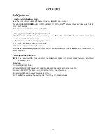
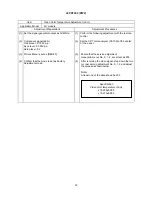
Preparation Procedure
(1) Input 576p or 480p adjustment signal
into AV4 terminal.
(1) Receive 576p or 480p adjustment signal on AV4
terminal input.
Indicate Service Adjustment Menu.
(2)
(3)
Select No.652 (RGB amplitude gain adjustment
Main) of Service Adjustment Menu.
Press [OK] key more than 2 seconds to start the
automatic adjustment.
The adjustment completes when the indication
[Auto Mode] at the bottom of the screen
disappears.
[Note] Never adjust without use of the specified signal.
If that were done by mistake, the picture would become abnormal in black level, contrast and color.
In this case, it will be recovered by re-adjustment in the specified way.
Black pattern: Set pedestal level.
Characters must not be inserted
into this signal.
Black White
0.7V
RGB Amplitude Adjustment (Main/Sub)
Select No.653 (RGB amplitude gain adjustment
Sub) of Service Adjustment Menu.
Press [OK] key more than 2 seconds to start the
automatic adjustment.
The adjustment completes when the indication
[Auto Mode] at the bottom of the screen
disappears.
[Note] Never adjust without use of the specified signal.
If that were done by mistake, the picture would become abnormal in black level, contrast and color.
In this case, it will be recovered by re-adjustment in the specified way.
Item
Applicable Model
All models
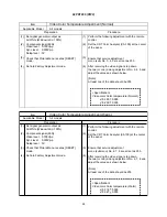
Preparation Procedure
(1) (1)
(2)
Black pattern: Set pedestal level.
Characters must not be inserted
into this signal.
Black White
0.7V
RGB Amplitude Adjustment (PC D-Sub input)
Input RGB amplitude adjustment signal of VGA
(60Hz) into RGB2 [D-sub] terminal.
Receive PC signal (VGA [60Hz]), and indicate
Service Adjustment Menu.(Main)
Select No.652 of Service Adjustment Menu.
Press [OK] key more than 2 seconds to start the
automatic adjustment.
The adjustment completes when the OSD
reappears.
Summary of Contents for 42PD7200
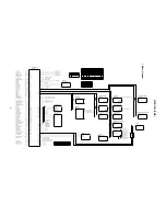
Page 10: ...9 42PD7200 PW2 Block diagram ...
Page 41: ...40 42PD7200 PW2 MEMO ...
Page 42: ...41 42PD7200 PW2 9 Basic circuit diagram 1 2 3 4 5 6 6 1 2 3 4 5 D A B C E F G ...
Page 43: ...42 42PD7200 PW2 1 2 3 4 5 6 6 1 2 3 4 5 D A B C E F G ...
Page 44: ...43 42PD7200 PW2 1 2 3 4 5 6 6 1 2 3 4 5 D A B C E F G ...
Page 45: ...44 42PD7200 PW2 1 2 3 4 5 6 6 1 2 3 4 5 D A B C E F G ...
Page 46: ...45 42PD7200 PW2 1 2 3 4 5 6 6 1 2 3 4 5 D A B C E F G ...
Page 47: ...46 42PD7200 PW2 1 2 3 4 5 6 6 1 2 3 4 5 D A B C E F G ...
Page 48: ...47 42PD7200 PW2 1 2 3 4 5 6 6 1 2 3 4 5 D A B C E F G ...
Page 49: ...48 42PD7200 PW2 1 2 3 4 5 6 6 1 2 3 4 5 D A B C E F G ...
Page 50: ...49 42PD7200 PW2 1 2 3 4 5 6 6 1 2 3 4 5 D A B C E F G ...
Page 51: ...50 42PD7200 PW2 1 2 3 4 5 6 6 1 2 3 4 5 D A B C E F G ...
Page 59: ...58 42PD7200 PW2 11 Block diagram ...
Page 63: ...62 42PD7200 PW2 Disassembly diagram 42V 13P CONNECTOR A5 2 Gasket Gasket ...
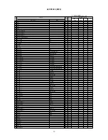
Page 66: ...THE UPDATED PARTS LIST FOR THIS MODEL IS AVAILABLE ON ESTA ...


