


10
42PD7200 (PW2)
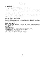
6. Adjustment
● How to get to Adjustment mode
Using the front control buttons with the set turned off (standby) can activate it.
Press the SUB-POWER(
) button, INPUT SELECT(
) button and button at the same time, and hold for
more than 5 seconds.
The set turns on in adjustment mode with OSD.
● Changing data and Selecting Adjustment code
When the set is in adjustment mode, the cursor , , , and OK buttons of the remote control or front panel
may be used as the adjustment keys.
, buttons are used for selecting adjustment code.
, buttons are used for changing data values.
OK button is used for confirming the data.
After finishing the necessary adjustment press MENU button. Adjustment mode is released and the set returns to
normal condition.
● Memory Initialize operation
NOTE:
The execution of this function returns the adjustment codes to the preset values, therefore, adjustment
data will be lost.
Procedure
(1) Enter Adjustment Mode.
(2) Select MEMORY INIT adjustment code (No.658) and change the data value from 0 to 1.
(3) Activate MEMORY INIT by pressing OK button for more than 3 seconds.
(4) Select No.525 and change data value from 1 to 0.
(5) Check that the receiving channel goes to P1. Unit is set to preset values.
Summary of Contents for 42PD7200
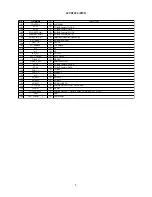
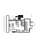
Page 10: ...9 42PD7200 PW2 Block diagram ...
Page 41: ...40 42PD7200 PW2 MEMO ...
Page 42: ...41 42PD7200 PW2 9 Basic circuit diagram 1 2 3 4 5 6 6 1 2 3 4 5 D A B C E F G ...
Page 43: ...42 42PD7200 PW2 1 2 3 4 5 6 6 1 2 3 4 5 D A B C E F G ...
Page 44: ...43 42PD7200 PW2 1 2 3 4 5 6 6 1 2 3 4 5 D A B C E F G ...
Page 45: ...44 42PD7200 PW2 1 2 3 4 5 6 6 1 2 3 4 5 D A B C E F G ...
Page 46: ...45 42PD7200 PW2 1 2 3 4 5 6 6 1 2 3 4 5 D A B C E F G ...
Page 47: ...46 42PD7200 PW2 1 2 3 4 5 6 6 1 2 3 4 5 D A B C E F G ...
Page 48: ...47 42PD7200 PW2 1 2 3 4 5 6 6 1 2 3 4 5 D A B C E F G ...
Page 49: ...48 42PD7200 PW2 1 2 3 4 5 6 6 1 2 3 4 5 D A B C E F G ...
Page 50: ...49 42PD7200 PW2 1 2 3 4 5 6 6 1 2 3 4 5 D A B C E F G ...
Page 51: ...50 42PD7200 PW2 1 2 3 4 5 6 6 1 2 3 4 5 D A B C E F G ...
Page 59: ...58 42PD7200 PW2 11 Block diagram ...
Page 63: ...62 42PD7200 PW2 Disassembly diagram 42V 13P CONNECTOR A5 2 Gasket Gasket ...
Page 66: ...THE UPDATED PARTS LIST FOR THIS MODEL IS AVAILABLE ON ESTA ...


