


36
42PD7200 (PW2)
8. Self-Diagnosis Function
This chassis has 2 modes of self-diagnosis function.
(1) PDP panel check mode: It indicates the one latest record of the PDP panel failure with blinking of the power
indication light (LED).
(2) Signal circuit check mode: It indicates the check result on some points of the signal circuit and the history of
them with On-Screen Display (OSD).
PDP panel self-diagnosis function
This function is for a PDP panel failure with no picture.
To enter to this Self-Diagnosis mode, follow the next steps:
Preparation:
1) The Power Cord should be connected to AC line and the Main Power switch should be turned on.
2) Turn the power off by the SUB-POWER(
) button of the monitor or the remote control.
Procedure:
1) Press the SUB-POWER(
) button and button on the bottom of the monitor at the same time, and keep it for
more than 5 seconds after the power turned on.
2) It generates red blinking series of the power indicator light.
3) Any operation would cancel the Self -Diagnosis mode.
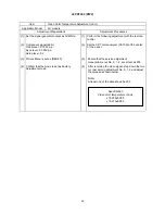
4) The next table shows the PDP PWB in which failure most probably would be allocated according to the
number of blinks.
Number of red blinks
Presumed failing PWB
of power indication light
of PDP panel
1
Logic
2
X-SUS
3
Y-SUS, SDM
SDM: Scan Driver Module
4
X-SUS, Y-SUS, SDM, PSU
PSU: Power Supply Unit
5
ABUS, ADM, PSU
ADM: Address Driver Module
6
ADM temperature
7
ADM temperature
8
All of above-mentioned
PWB’s
Note) SDM is permanently contacted to glass part
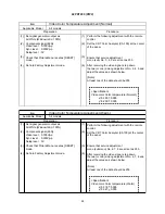
[Blinking condition of power indication light]
Ex. 2 blinks
1 sec
1 sec
2 sec OFF
Repeat
Summary of Contents for 42PD7200
Page 10: ...9 42PD7200 PW2 Block diagram ...
Page 41: ...40 42PD7200 PW2 MEMO ...
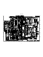
Page 42: ...41 42PD7200 PW2 9 Basic circuit diagram 1 2 3 4 5 6 6 1 2 3 4 5 D A B C E F G ...
Page 43: ...42 42PD7200 PW2 1 2 3 4 5 6 6 1 2 3 4 5 D A B C E F G ...
Page 44: ...43 42PD7200 PW2 1 2 3 4 5 6 6 1 2 3 4 5 D A B C E F G ...
Page 45: ...44 42PD7200 PW2 1 2 3 4 5 6 6 1 2 3 4 5 D A B C E F G ...
Page 46: ...45 42PD7200 PW2 1 2 3 4 5 6 6 1 2 3 4 5 D A B C E F G ...
Page 47: ...46 42PD7200 PW2 1 2 3 4 5 6 6 1 2 3 4 5 D A B C E F G ...
Page 48: ...47 42PD7200 PW2 1 2 3 4 5 6 6 1 2 3 4 5 D A B C E F G ...
Page 49: ...48 42PD7200 PW2 1 2 3 4 5 6 6 1 2 3 4 5 D A B C E F G ...
Page 50: ...49 42PD7200 PW2 1 2 3 4 5 6 6 1 2 3 4 5 D A B C E F G ...
Page 51: ...50 42PD7200 PW2 1 2 3 4 5 6 6 1 2 3 4 5 D A B C E F G ...
Page 59: ...58 42PD7200 PW2 11 Block diagram ...
Page 63: ...62 42PD7200 PW2 Disassembly diagram 42V 13P CONNECTOR A5 2 Gasket Gasket ...
Page 66: ...THE UPDATED PARTS LIST FOR THIS MODEL IS AVAILABLE ON ESTA ...


