


24
42PD7200 (PW2)
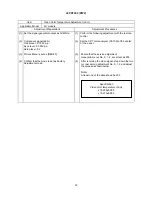
Item
Applicable Model
All models
Preparation Procedure
(1) Set signal generator output as
All White (Window ratio: 100%).
(1)
(2) Component signal (480i)
Video level : 0.700Vp-p
Sync level : 0.300Vp-p
Setup level : 0V
(2)
<Specification>
Video color Color temperature (Normal)
x=0.285
0.005
y=0.293
0.005
(3)
(4)
Check that Picture Menu is set as [RESET]
mode.
(3)
(4)
Video Color Temperature Adjustment (Normal)
Perform the following adjustment with the remote
control.
Set the CRT Color Analyzer (CA-100) at the center
of the panel.
Ensure that service adjustment
menu (sub) No. 3, 4, 5 are all set as 255.
After receiving the video signal, step down
the two (or one) among adjustment No. 3, 4, 5 and
adjust the values as shown below.
(Note)
At least one of the data should be 255.
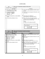
Item
Applicable Model
All models
Preparation Procedure
(1) Set signal generator output as
All White (Window ratio: 100%).
(1)
(2) Component signal (480i)
Video level : 0.700Vp-p
Sync level : 0.300Vp-p
Setup level : 0V
(2)
<Specification>
Video color Color temperature (Warm)
x=0.314
0.005
y=0.327
0.005
(3)
(4)
Check that Picture Menu is set as [RESET]
mode.
(3)
(4)
Video Color Temperature Adjustment (Warm)
Perform the following adjustment with the remote
control.
Set the CRT Color Analyzer (CA100) at the center
of the panel.
Ensure that service adjustment
menu (submenu) No. 6, 7, 8 are all set as 255.
After receiving the video signal, step down
the two (or one) among adjustment No. 6, 7, 8 and
adjust the values as shown below.
(Note)
At least one of the data should be 255.
Set into Factory Adjustment mode.
Set into Factory Adjustment mode.
Summary of Contents for 42PD7200
Page 10: ...9 42PD7200 PW2 Block diagram ...
Page 41: ...40 42PD7200 PW2 MEMO ...
Page 42: ...41 42PD7200 PW2 9 Basic circuit diagram 1 2 3 4 5 6 6 1 2 3 4 5 D A B C E F G ...
Page 43: ...42 42PD7200 PW2 1 2 3 4 5 6 6 1 2 3 4 5 D A B C E F G ...
Page 44: ...43 42PD7200 PW2 1 2 3 4 5 6 6 1 2 3 4 5 D A B C E F G ...
Page 45: ...44 42PD7200 PW2 1 2 3 4 5 6 6 1 2 3 4 5 D A B C E F G ...
Page 46: ...45 42PD7200 PW2 1 2 3 4 5 6 6 1 2 3 4 5 D A B C E F G ...
Page 47: ...46 42PD7200 PW2 1 2 3 4 5 6 6 1 2 3 4 5 D A B C E F G ...
Page 48: ...47 42PD7200 PW2 1 2 3 4 5 6 6 1 2 3 4 5 D A B C E F G ...
Page 49: ...48 42PD7200 PW2 1 2 3 4 5 6 6 1 2 3 4 5 D A B C E F G ...
Page 50: ...49 42PD7200 PW2 1 2 3 4 5 6 6 1 2 3 4 5 D A B C E F G ...
Page 51: ...50 42PD7200 PW2 1 2 3 4 5 6 6 1 2 3 4 5 D A B C E F G ...
Page 59: ...58 42PD7200 PW2 11 Block diagram ...
Page 63: ...62 42PD7200 PW2 Disassembly diagram 42V 13P CONNECTOR A5 2 Gasket Gasket ...
Page 66: ...THE UPDATED PARTS LIST FOR THIS MODEL IS AVAILABLE ON ESTA ...


