background image

Troubleshooting

26 


ML12E User Manual, 99151B, September 2021

Touch Screen Troubleshooting

Applies to touch screen monitors only�  To be sure that you have the most current driver, please 

check the following Internet address:

https://www�HopeIndustrial�com/support/drivers/
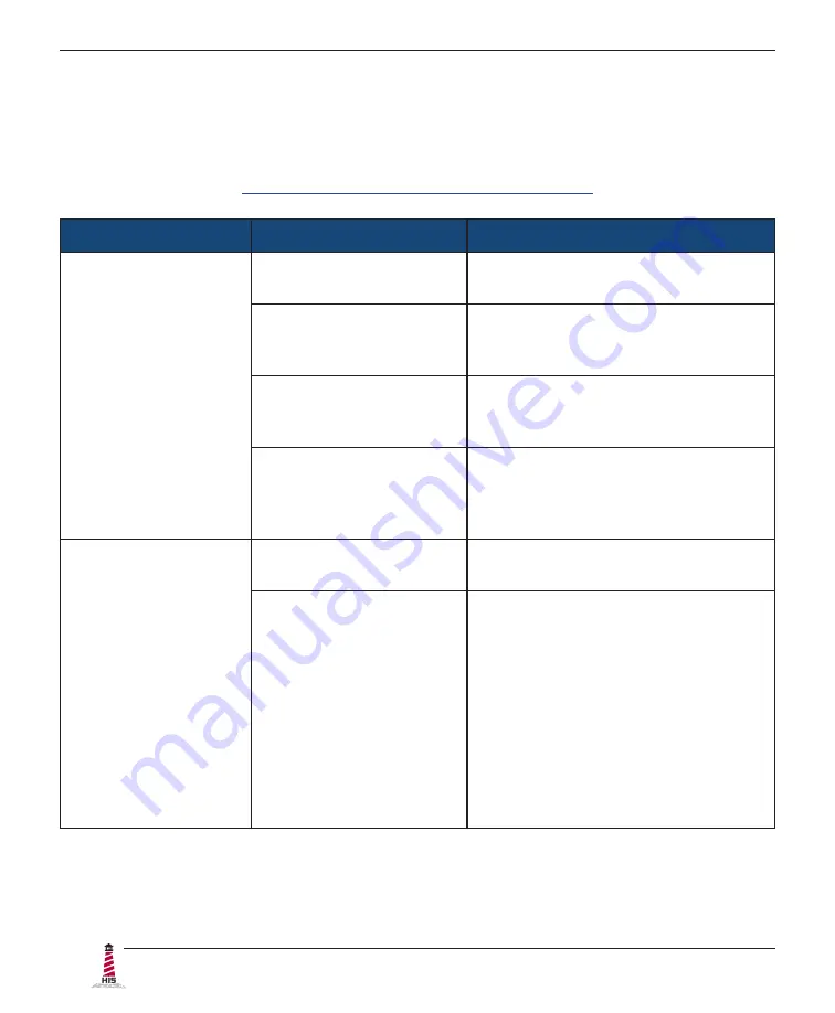
Symptom

Causes

Solutions

No response when 

touching the touch 

screen

Touch screen driver has 

not been installed�

Download and install the latest driver 

from the Hope Industrial website�

Touch screen cable is not 

plugged in correctly.

Make sure either the USB or Serial 

cable is securely connected to the 

monitor and PC�  Do not connect both�

If using a USB connection, 

does the USB cable length 

exceed 5 meters?

USB cables have a 5 meter limitation 

and could cause no touch response if 

this is exceeded�

If using a Serial 

connection, is the Serial 

cable plugged into the 

correct COM port?

Ensure that the Serial cable is 

connected to the COM port being used 

prior to installing the touch screen 

driver�

The cursor moves 

but does not follow 

my finger when 

touching the touch 

screen

Touch screen driver has 

not been installed�

Download and install the latest driver 

from the Hope Industrial website�

Touch screen has not 

been calibrated�

Activate the calibration utility�  In 

Windows systems, these settings may 

be found at the following location:

Control Panel  >  Elo Touchscreen  >  

"General" Tab

• 

Press the Align button.

• 

Touch all targets as the appear to 

calibrate the touch screen�

•  Press the Green Check button 

when verified.

Summary of Contents for HIS-ML12 E Series

Page 1: ...12 PANEL MOUNT INDUSTRIAL MONITOR USER MANUAL Model No HIS ML12 _ _ _ E REVISION E ...

Page 2: ...Step 2 Bench test Configuration 8 Install Cable Connections 8 Install Touch Screen Driver 10 Step 3 Install into Panel 12 Video Settings 14 Setting the Timing Mode 14 Control Panel Buttons 15 On Screen Display OSD Menus 17 Picture Menu 17 VGA Settings Menu 19 Setup Menu 20 Cleaning Instructions 23 Troubleshooting 24 Video Troubleshooting 24 Touch Screen Troubleshooting 26 Specifications 27 Display...

Page 3: ...talled in a like rated enclosure DC Supplied Units only The HISML12 subject unit is to be powered by a Listed Power Supply suitable for the application with outputs at SELV LPS or Class 2 levels rated 9 6 36 6VDC 2 5 A max The equipment is not intended to connect directly to a DC Mains source FCC Notice This equipment has been tested and found to comply with the limits for a Class A digital device...

Page 4: ... Class I Division 2 Groups A B C and D Class II Division 2 Groups F and G Class III or non hazardous locations only Device is open type and is to be installed in an enclosure suitable for the environment that is only accessible with the use of a tool FR Cet équipement peut être utilisé dans la Classe I Division 2 Groupes A B C et D Classe II Division 2 Groupes F et G et Classe III endroits hasarde...

Page 5: ...ings Front and Side Views Bottom View 7 1 mm 0 28 216 1 mm 8 51 295 7 mm 11 64 338 1 mm 13 31 249 mm 9 8 188 mm 7 4 269 4 mm 10 61 338 1 mm 13 31 7 1 mm 0 28 55 0 mm 2 16 Design to maximum depth of 63 5 mm to ensure future compatibility with later revisions and replacement units ...

Page 6: ...Mechanical Drawings 6 ML12E User Manual 99151B September 2021 Rear View MENU SEL 75 mm VESA Mounting Pattern M4 screws provided 16 mm maximum depth of screw ...

Page 7: ...0 C 122 F f Remember that heat rises the temperature at the top of the cabinet will be much hotter than at the bottom if air inside the enclosure is not actively circulating Even in a sealed enclosure use of a circulation fan can greatly reduce temperature f Also remember that even though this product is designed to operate at 50 C the life span of any electronic device is shortened when it is con...

Page 8: ...em issues while configuration changes may still be easily made Install Cable Connections All monitors are shipped with a standard VGA video cable AC powered displays are also shipped with a power mains cable If you ordered a touch screen monitor a USB cable is supplied for the touch screen interface To use the touch screen Serial RS 232 interface a serial cable may be ordered separately The cable ...

Page 9: ...layPort connection this can be converted for use with the DVI video port using a simple adapter If the video source has a 5 wire analog RGB video output this can be converted for use with the VGA video port using a simple adapter Certified adapters are available from Hope Industrial Systems Contact our sales team for more information Power Connection The HIS ML12 is available with either AC or DC ...

Page 10: ...Hope Industrial Systems if you require a CD ROM with documentation and drivers for touch screens For a full list of downloadable drivers please check the following Internet address https www HopeIndustrial com support drivers IMPORTANT If you will be using a USB connection install the touch screen driver first and then connect the USB cable If you will be using a Serial connection connect the Seri...

Page 11: ...w locks on the cable connectors to ensure adequate strain relief HAZ LOC NOTE If this step is not performed the product will not comply with Class I II III Division 2 Hazardous Location requirements 2 Select the appropriate driver for your operating system from the web address listed above 3 Click to Run the software when prompted Follow on screen instructions to download and execute the touch scr...

Page 12: ... the panel Allow extra space 12 7 mm 0 5 behind and on each side for air ventilation Step 3 Install into Panel Once you have completed the full bench test configuration and confirmed that all components are working properly you are ready to install the monitor into its panel cutout WARNING Hope Industrial Systems will not assume liability for damage to internal electronics due to improper installa...

Page 13: ...below 7 Insert the unit into the front of the panel and re attach the collar NOTE Contact Hope Industrial Systems if for any reason your application does not allow for installation of the collar 8 Tighten all 8 nuts to a torque of 10 15 inch pounds to ensure a watertight seal between the bezel gasket on the monitor and the equipment panel Go around all nuts twice to ensure an even compression on g...

Page 14: ... setting the timing mode use the On Screen Display OSD controls to adjust the screen image TIP For the best picture quality set your computer graphics adapter timing mode to VESA 800 x 600 60 Hz Please refer to the computer graphics adapter manufacturer s manual for instructions on setting the resolution and timing mode In Microsoft Windows these settings may be found at the following location f 2...

Page 15: ...atically after 60 seconds This is adjustable through the OSD Time out setting in the Setup menu 2 To navigate through the main OSD menu press the left or right button 3 To select a control to adjust press the Select SEL button to navigate down through the menu 4 To adjust a selected control press the left or right button or press the right button to open the submenu for a selected control 5 To ret...

Page 16: ...stment When the OSD menu IS displayed Navigates left in the main OSD menu Decreases adjustments for the selected control Right Up Input Source When the OSD menu IS NOT displayed Shortcut to select input source When the OSD menu IS displayed Navigates right in the main OSD menu Displays the submenu for the selected control Increases adjustments for the selected control Power Indicator Light LED lit...

Page 17: ...he Inputs OSD Info Reset to factory defaults Source scan and Advanced Setup functions Picture Menu The Picture menu includes the Contrast Brightness Sharpness and Color functions Picture Menu Description Contrast Adjusts the difference between the image background black level and the foreground white level Brightness Adjusts the background black level of the screen image This feature may also be a...

Page 18: ...ntent white red blue green Please contact our support team for further details NOTE The Auto color function is only available when using the analog VGA connector Theme mode Allows the user to select from three image modes for different usage as well as the default Off setting Multimedia optimizes the screen for multimedia applications such as video playback Desktop optimizes the screen for desktop...

Page 19: ...o the screen for warmer white and richer red Normal is the factory default setting Cold adds blue to the screen image for cooler white VGA Settings Menu The VGA Settings menu includes the Timing Auto setup H total V position H position and Phase functions VGA Settings Menu Description Timing Displays the timing mode video signal input coming from the graphics card in the computer Auto setup Automa...

Page 20: ... image up and down H position Horizontal Position Moves the screen image left and right Phase Adjusts the focus of the screen image Allows the user to remove any horizontal noise and sharpen the image of characters Setup Menu The Setup menu includes the Inputs OSD Info Reset to factory defaults Source scan and Advanced Setup functions Setup Menu Description Inputs Allows the user to select between...

Page 21: ...guage used in the menus and control screens Rotation allows the user to rotate the OSD by 0 90 180 or 270 A Mirrored setting is also available which is a horizontal reflection of the OSD OSD Position allows the user to move the OSD by its x Position or y Position Show Logo allows the user to disable the power on splash screen Info Displays the monitor s Software Software Revision Timing mode and M...

Page 22: ...Advanced Setup submenu contains two additional settings Smart ISP flashes the video board firmware Do not activate without assistance from Hope Industrial technical support CVT Mode set to On will force the display to only render VESA CVT standard signals When set to Off the default setting the display will use its entire internal lookup table when syncing to an incoming video signal CVT Mode shou...

Page 23: ...ATCH THE PROTECTIVE COATING ALWAYS USE A SOFT CLOTH PREFERABLY MADE OF COTTON All displays may be cleaned using any standard glass cleaner as long as there is no abrasive or oily content Vinegar or ammonia will not hurt the screen The anti reflective coatings on glass window equipped displays are physically part of the surface of the glass and resist degradation to the Military Specifications ...

Page 24: ...voltage is 9 6 to 36 6 VDC No image on the screen and control s Power Indicator light is lit solid red Monitor is not powered on Press the Power button on the monitor for 1 2 seconds to turn the monitor on and make sure the Power Indicator light is lit green No image on the screen and control s Power Indicator light is blinking orange or blinking green Video cable is not plugged in correctly Check...

Page 25: ...unction may also be activated by pressing the Select SEL button outside of the OSD menu Fine tune the picture by manually adjusting the image using the settings in the OSD menu Analog signal is not a standard CVT signal this does not apply to digital signals Disable the CVT Mode function in the Advanced Setup menu located in the OSD s Setup menu This allows the monitor to use the controller board ...

Page 26: ... the USB cable length exceed 5 meters USB cables have a 5 meter limitation and could cause no touch response if this is exceeded If using a Serial connection is the Serial cable plugged into the correct COM port Ensure that the Serial cable is connected to the COM port being used prior to installing the touch screen driver The cursor moves but does not follow my finger when touching the touch scre...

Page 27: ...osure Type Panel mount rear collar compresses gasket against panel 5 16 maximum panel thickness held by 8 M5 studs Panel Rating with proper installation Built to IP65 IP66 standards NEMA UL Type 12 4 4X Depth Total Product Depth 55 0 mm 2 16 Depth Behind Front Edge of Panel 46 2 mm 1 82 NOTE Design to maximum depth of 63 5 mm 56 5 mm behind front edge of panel to ensure future compatibility with l...

Page 28: ...all for details Horizontal Scan 30 60 kHz Vertical Scan 50 75 Hz Supported Video Standards 800 x 600 56 60 72 75 Hz 800 x 480 60 Hz 720 x 480 60 Hz 720 x 400 70 Hz 640 x 480 60 67 72 75 Hz 640 x 400 70 Hz Response Rate typical 12 ms Functional Control Panel Buttons Menu SEL Navigate Down Auto setup Left Down Brightness Adjustment Right Up Input Source Power On Screen Display OSD Menus Contrast Bri...

Page 29: ...15 g 6 msec half sine Operating Vibration sine 1 0g swept sine 9 500 Hz Transport Vibration random 0 1g2 Hz 10 200 Hz 0 03g2 Hz 200 2000 Hz Altitude Operating up to 10 000 feet Non operating up to 40 000 feet Electrical Monitor Input AC power models 100 to 240 VAC 0 4 0 2 A 60 50 Hz DC power models 9 6 to 36 6 VDC 2 5 to 0 65 A Class 2 or SELV LPS Power Consumption 14 9 W Power Consumption Standby...

Page 30: ...M Registration No NOM 019 SCFI 1998 Environmental IEC 60721 3 Reliability WEEE Registration No WEE DJ1859ZX for UK only Enclosure UL 50E File No E318630 Hazardous Location UL Rated for Hazardous Locations Industrial Control Equipment for Hazardous Location Listed for Class I Division 2 for Groups A B C and D Class II Division 2 for Groups F and G Class III Temp Code T4A File No E328481 per UL12120...

Page 31: ...ded we will give you a Return Material Authorization RMA number This RMA number must be conspicuously marked on the outside of the shipping box Hope Industrial Systems will not accept shipments not accompanied by the RMA number Except where otherwise noted you must ship or deliver the product to Hope Industrial Systems Freight prepaid What Does This Warranty Not Cover This warranty does not cover ...

Page 32: ... 44 0 20 7193 2618 HopeIndustrial fr Germany Phone 44 0 20 7193 2618 HopeIndustrial de Italy Phone 39 80 0740414 HopeIndustrial it Spain Phone 34 91 1438229 HopeIndustrial es EU Authorized Representative Falcons Logistics B V Hoeksteen 26 F 2132 MS Hoofddorp Netherlands HopeIndustrial eu United Kingdom Authorized Representative Falcon AR Services UK LTD Lynton House 7 12 Tavistock Square WC1H 9LT ...

Reviews: