Hipo INKJET plotter manual
18
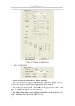
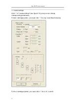
Figure 7-6 nozzle settings
A, B, C, D represents the actual location of the corresponding nozzles,
options are A, B, C, D (Single-nozzle mode); A+B
、
B+C
、
C+D (Double nozzle
mode); A+B+C
、
B+C+D (Three-nozzle mode); A+B+C+D (Four-nozzle mode);
altogether ten modes.
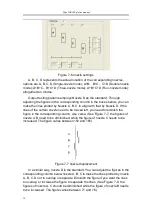
Output testing patterns employs Nozzle D as the standard. Through
adjusting the figures in the corresponding column in the boxes below, you can
make the lines plotted by Nozzle A, B, C to align with that by Nozzle D. If the
lines of the certain nozzle need to be moved left, you need to diminish the
figure in the corresponding column, vise versa. (See Figure 7-7, the figures of
nozzle A, B need to be diminished, while the figure of nozzle C needs to be
increased. The figure varies between 150 and 165)
Figure 7-7 nozzle displacement
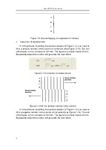
In a similar way, nozzle D is the standard. You can adjust the figures in the
corresponding column below nozzle A, B, C to make the lines plotted by nozzle
A, B, C. D not to overlap or separate. Diminish the figure if you want the lines
to overlap, or increase the figure to separate the lines. (See Figure 7-9, the
figures of nozzle A, C should be diminished while the figure of nozzle B needs
to be increased. The figure varies between 71 and 76.)


