background image

1/3

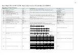
Super Megohm Meter SM7110,7120 Programming Command Compatibility with DSM8104

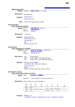
Setting Control Program Messages

DSM8104

Function

Format

Compatibility Notes

SM7110、SM7120

DLM

Delimiter designation in talker mode.

DLM <0~2>

・Specifying "2:<EOI>" will result in a setting of "0:LF<EOI>."
• Because this setting is backed up, cycling the power will Not cause the default value to be restored.

:SYSTem:TERMinator <LF/CRLF>

DLM?

Delimiter query.

DLM?

· Because the instrument does Not support the "2:<EOI>" setting, the response will be "0."

:SYSTem:TERMinator?

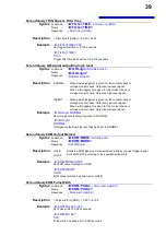
DFM

Output data format designation.

DFM <0~3>

Not compatible

DFM?

Query response in output data format.

DFM?

Not compatible

MOD

Measuring mode setting.

MOD <0~3>

:MEASure:MODE <R/A/RS/RV/RL>

MOD?

Query response in screen state is same as setting.

MOD?

• When the instrument is set to liquid volume resistivity measurement mode, this query will result in a response of

:MEASure:MODE?

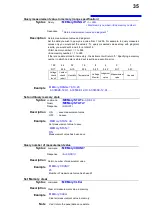
MON

Changeover between regular measurement.

MON <0~1>

:DISPlay:MODE <NORMal/SEQuence>

MON?

Query response in measuring mode is same as setting.

MON?

:DISPlay:MODE?

LCD

LCD display mode setting.

LCD <0~1>

• Specifying "0" will set the LCD and backlight to 0 and disable measured value render updates.
• Specifying "1" will set the LCD to 50 and the backlight to 80 and enable measured value render updates.

:DISPlay:CONTrast <0~100(NR1)>
:DISPlay:BACKlight <0~100(NR1)>
:DISPlay:UPDate <ON/OFF>

LCD?

Query response in LCD display mode is same as setting.

LCD?

• The instrument will return "0" if the LCD and backlight are set to 0 and measured value render updates are
disabled.
• Otherwise, it will return "1."

:DISPlay:CONTrast?
:DISPlay:BACKlight?
:DISPlay:UPDate?

FIG

Setting number of effective columns for measured value display.

FIG <2~5>

• Specifying "2" will cause the command to be igNored.

:MEASure:DIGit <3~6(NR1)>

FIG?

Query response on setting number of effective columns for measured
value display is same as setting.

FIG?

• Because the instrument does Not support the "2" setting, the response will be a value from "3" to "6."

:MEASure:DIGit?

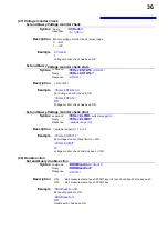
DSP

Display mode setting.

DSP <0~1>

:MEASure:FORMat <UNIT/EXP>

DSP?

Query response in display mode is same as setting.

DSP?

:MEASure:FORMat?

DLY

Trigger delay time (ms) setting.

DLY <0~9999>

:DELay <Delay time(s)(NR2)>

DLY?

Query response on trigger delay time is same as setting.

DLY?

:DELay?

AVE

Averaging setting.

AVE <0~1>

• Specifying "1" will cause the auto averaging function to be set.
• Specifying "2: will cause the average hold function to be set (Not supported by the DSM8104).

:AVERage <OFF/HOLD/AUTO>

AVE?

Query response in averaging is same as setting.

AVE?

• When the average hold function is enabled, this query will result in a response of "2."

:AVERage?

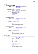
SPL

Integral time setting (Unit, set values).

SPL <0~1>,<1~15>/<2~
300>

• Different combinations of units and settings can be used to make the settings listed in the following table

:SPEEd <SLOW2/SLOW/MED/FAST2/FAST>

SPL?

Query response on setting number of integral time (unit, set value) is
same as setting.

SPL?

• The response will vary with the instrument’s SPEED setting as described in the following table:

:SPEEd?

RNG

Current range setting.

RNG <0~1>,<0~7>

• The instrument will be configured as described in the following table based on its SPEED setting:

:RANGe <20pA/200pA/2nA/20nA/200nA/2uA/20uA/200uA/2mA>

RNG?

Query response on current range is same as setting

RNG?

• The response (HOLD) will vary with the instrument’s SPEED setting as described in the following table:

:RANGe?

■0:PLC setting
PLC

1~3

4~12

13~15

SPEED

MED

SLOW

SLOW2

■1:ms setting
ms(Line frequency50Hz)

2~9

10~19

20~79

80~259 260~300

SPEED

FAST

FAST2

MED

SLOW

SLOW2

ms(Line frequency60Hz)

2~7

8~15

16~65

66~215 216~300

SPEED

FAST

FAST2

MED

SLOW

SLOW2

SPEED

FAST

FAST2

MED

SLOW

SLOW2

Response

1,2

1,10(50Hz)
1,8(60Hz)

0,1

0,4

0,13

Range setting during

FAST

FAST2

MED

SLOW

SLOW2

0

2mA

2mA

2mA

Change

2mA

Change

200uA

1

2mA

200uA

200uA

200uA

20uA

2

200uA

20uA

20uA

20uA

2uA

3

20uA

2uA

2uA

2uA

200nA

4

2uA

200nA

200nA

200nA

20nA

5

200nA

20nA

20nA

20nA

2nA

6

20nA

2nA

2nA

2nA

20pA

7

2nA

2nA

200pA

20pA

20pA

SM7420 Range setting

FAST

FAST2

MED

SLOW

SLOW2

2mA

0,1

0,0

200uA

0,2

0,1

0,1

0,1

0,0

20uA

0,3

0,2

0,2

0,2

0,1

2uA

0,4

0,3

0,3

0,3

0,2

200nA

0,5

0,4

0,4

0,4

0,3

20nA

0,6

0,5

0,5

0,5

0,4

2nA

0,7

0,6

0,6

0,6

0,5

200pA

0,7

0,6

0,6

20pA

0,7

0,7

Summary of Contents for Super megohm SM7110

Page 1: ... command settings Although all reasonable care has been taken in the production of this manual should you find any points which are unclear or in error please contact your local distributor or the HIOKI International Sales Department at os com hioki co jp In the interest of product development the contents of this manual may be subject to revision without notice Unauthorized copying and replicatio...

Page 2: ... 16 4 Status and Event Control Commands 16 CLS 16 ESE 16 ESR 16 SRE 17 STB 17 TRG 17 Device Specific Commands 18 1 Measurement status 18 STARt 18 STOP 18 STOP CONDition 18 STATe 18 2 Reading Measured Values 19 MEASure 19 MEASure COMParator 19 MEASure RESult 19 MEASure CLEar 19 3 Voltage Monitor 20 MEASure MONItor 20 4 Tempureture and Humidity value 20 MEASure TEMPerature 20 MEASure HUMidity 20 5 M...

Page 3: ...7 18 Current Limit 27 CHARge LIMit 27 CHARge LIMit CURRent 28 19 Contact check 28 CONTactcheck FREQuency 28 CONTactcheck WORKc 28 CONTactcheck CABLe 28 CONTactcheck CABLe AUTO 29 CONTactcheck DELay 29 OPEN 29 OPEN VALue 29 CONTactcheck STATe 30 CONTactcheck LIMit 30 CONTactcheck 30 CONTactcheck VALue 30 20 Drawing update during measurement 31 DISPlay UPDate 31 21 Resistivity measurement function 3...

Page 4: ... DISPlay BACKlight 37 30 Line Frequency 37 SYSTem LFRequency 37 SYSTem LFRequency AUTO 38 31 Reset 38 RESet 38 32 EXT I O 38 IO EDGE 38 IO FILTer STATe 38 IO FILTer TIME 39 IO GOLogic 39 IO EOM MODE 39 IO EOM PULSe 39 IO OUTPin 40 IO MODE 40 33 Device Event Status Enable Register 40 DSE0 40 DSR 40 34 Command Header 41 HEADer 41 35 Communications Settings 41 SYSTem LOCal 41 SYSTem TERMinator 41 4 M...

Page 5: ...Program Messages Query Messages Messages Response Message When issuing commands that contain data make sure that the data is provided in the specified format Message Format Program Messages Program messages can be either Command Messages or Query Messages 1 Command Messages Instructions to control the instrument such as to change settings or reset Example instruction to set the measurement average...

Page 6: ...ase sensitive in actual usage CALibration OK long form CALIBRATION OK long form CAL OK short form CALIB Error CA Error Response messages generated by the instrument are in long form and in upper case letters Headers Headers must always be prefixed to program messages 1 Command Program Headers There are three types of commands Simple Compound and Standard Headers for Simple Commands This header typ...

Page 7: ...c data and character string data depending on the command 1 Character Data Character data always begins with an alphabetic character and subsequent characters may be either alphabetic or numeric Character data is not case sensitive although response messages from the instrument are only upper case When the command data portion contains 1 0 ON OFF the operation will be similar to when 0 is OFF and ...

Page 8: ...ed from the messages immediately following The current path is cleared when the power is turned on when reset by key input by a colon at the start of a command and when a message terminator is detected Standard command messages can be executed regardless of the current path They have no effect upon the current path A colon is not required at the start of the header of a Simple or Compound command ...

Page 9: ...he Master Summary Status of the Status Byte Register is also set Status Byte Register STB When any Status Byte Register bit enabled by the Service Request Enable Register has switched from 0 to 1 the MSS bit becomes 1 Although the MSS bit is only read by an STB query it is not cleared until a clear event is initiated by the CLS command Bit 7 ERR Bit 6 MSS This is the logical sum of the other bits ...

Page 10: ...rameters Invalid parameter format Received a command not supported by the instrument Bit 4 EXE Execution Error This bit is set to 1 when a received command cannot be executed for some reason The specified data value is outside of the set range The specified setting data cannot be set Execution is prevented by some other operation being performed Bit 3 Unused DDE Device Dependent Error This bit is ...

Page 11: ...enabled by its corresponding Event Status Enable Register is set to 1 Status Byte Register bit 3 DSB is set to 1 Event Status Registers are cleared in the following situations When a CLS command is executed When an Event Status Register query DSR is executed When the instrument is powered on Device Event Status Register DESR Bit 7 Unused Bit 6 Unused Bit 5 BOV Measured data buffer overflow Set whe...

Page 12: ...t3 bit2 bit1 bit0 Unused Unused BOV BFL STP ITL LM2 LM1 Device Event Status Enable Register DESER Register Reading and Writing Register Read Write Status Byte Register STB Service Request Enable Register SRE SRE Standard Event Status Register ESR Standard Event Status Enable Register ESE ESE Device Event Status Register 0 DSR Device Event Status Enable Register 0 DSE DSE Initialization Items Initi...

Page 13: ...rocessed sequentially In communications with the controller time must be added for data transmission Transfer time depends on the controller The Transfer time with start bit 1 data length 8 no parity and stop bit 1 has a total of 10 bit When the transfer speed baud rate setting is N bps the general result will be as follows Transfer time T 1 character sec Baud rate N bps 10 bits If a measurement v...

Page 14: ...uery Judgment of Measured Value MEASure RESult Query Measurement value and Judgment MEASure CLEar Clear Measuremt Value and Judgment Value Voltage Monitor MEASure MONItor Query Voltage Monitor value Tempureture and Humidity value MEASure TEMPerature Query Tempureture value MEASure HUMidity Query Humidity value Measured value display mode MEASure MODE Set Measured value display mode MEASure MODE Qu...

Page 15: ...ion Execute and Query Self Calibration CALibration AUTO Set Self Calibration AUTO CALibration AUTO Query Self Calibration AUTO CALibration TIME Set Self Calibration time CALibration TIME Query Self Calibration time Interlock INTerlock Set Interlock state INTerlock Query Interlock state Current Limit CHARge LIMit Set current limit CHARge LIMit Query current limit CHARge LIMit CURRent Set total curr...

Page 16: ...data Key Beeper KEY BEEPer Set Key Beeper KEY BEEPer Query Key Beeper Key lock SYSTem KLOCk Set Key Lock State SYSTem KLOCk Query Key Lock State Internal memory MEMory Query measurement value in memory MEMory RANGe Query measurement value in memory range specification MEMory STATe Set memory state MEMory STATe Query memory state MEMory COUNt Query number of measurement value MEMory CLEar Set Memor...

Page 17: ...OM MODE Set EOM Output Method IO EOM MODE Query EOM Output Method IO EOM PULSe Set EOM Pulse Width IO EOM PULSe Query EOM Pulse Width IO OUTPin Query Output Pin Status IO MODE Query NPN PNP Switch Status Device Event Status Enable Register DSE Set Device Event Status Enable Register DSE Query Device Event Status Enable Register DSR Query Device Event Status Register Command header HEADer Set Heade...

Page 18: ...nd data or response message Describes the message Shows an example of an actual command application Normally described with HEADER OFF except the HEADER command itself Read Write the Standard Event Status Enable Register SESER Syntax Command ESE 0 to 255 NR1 Query ESE Response 0 to 255 NR1 Description Command The SESER mask is set to the numerical value 0 to 255 The initial value at power on is 0 ...

Page 19: ...All Pending Operations Syntax Command OPC Description Sets OPC bit 0 of the Standard Event Status Register SESR when all commands prior to OPC have finished processing Example A B OPC C The OPC bit of SESR is set after A and B command processing has been completed Respond with ASCII 1 when Finished with All Pending Operations Syntax Query OPC Response 1 Description Response with ASCII 1 when all c...

Page 20: ...he event status registers are also cleared STB SESR DESR Note The output queue is unaffected Set and Query Standard Event Status Enable Register SESER Syntax Command ESE 0 to 255 NR1 Query ESE Response 0 to 255 NR1 Description Command The SESER mask is set to the numerical value 0 to 255 The initial value at power on is 0 Query The contents of the SESER as set by the ESE command are returned as an...

Page 21: ... 1 bit 0 ERR 0 ESB MAV DSB Unused Unused MEC Example SRE 33 Set SRER bits 0 and 5 to 1 SRE 33 SRER bits 0 and 5 have been set to 1 Query Status Byte and MSS Bit Syntax Query STB Response 0 to 255 NR1 Description The contents of the STB are returned as an NR1 value 0 to 255 The response message has no header 128 64 32 16 8 4 2 1 bit 7 bit 6 bit 5 bit 4 bit 3 bit 2 bit 1 bit 0 ERR MSS ESB MAV DSB Un...

Page 22: ...Syntax Command STOP CONDition DISCharge HIZ Query STOP CONDition Response DISCHARGE HIZ Description DISCharge Discharge HIZ High inpeadance Example STOP CONDition DISCharge Setting the Discharge mode STOP CONDition DISCHARGE Now Setting is Discharge mode Query measurement status Syntax Query STATe Response 0 4 NR1 Description Response Normal mode Sequence mode 0 Stop Stop 1 Trigger wait Discharge1...

Page 23: ... value and Judgment Syntax Query MEASure RESult 1 255 Response Measurent value and judgment value Description Return the measurement value and judgment value for camma Rrsponse data is set to 0 to 255 128 64 32 16 8 4 2 1 bit 7 bit 6 bit 5 bit 4 bit 3 bit 2 bit 1 bit 0 Voltage check result Contact check result Humidity Tempereture Voltage Monitor Judgment value Measurement value Unused Example MEA...

Page 24: ...e MEASure TEMPerature 23 45 Tempureture has been 23 45 Query Humidity value Syntax Query MEASure HUMidity Response Humidity rh NR2 Description Return humidity value When Z2011 has not set return humidity value has been 99 99 Example MEASure HUMidity 50 1 Humidity has been 50 1 rh 5 Measured value display mode Set and Query Measured value display mode Syntax command MEASure MODE R A RS RV RL Query ...

Page 25: ...ber of displayed digits to 3 MEASure DIGit 3 The number of displayed digits has been 3 8 Applied Voltage Set and Query Applied Voltage Syntax command VOLTage Applied Voltage V NR2 Query VOLTage Response Applied Voltage V NR2 Description SM7110 Applied Voltage V NR2 0 1 1000 0 SM7120 Applied Voltage V NR2 0 1 2000 0 Example VOLTage 100 Set to Applied Voltage to 100V VOLTage 100 Applied Voltage has ...

Page 26: ... to ON RANGe AUTO ON Auto range has been set to ON 11 Delay Set and Query Delay time Syntax command DELay Delay time s NR2 Query DELay Response Delay time s NR2 Description Delay time s NR2 0 0 999 9 Example DELay 12 3 Set delay time to 12 3 seconds DELay 12 3 Delay time has been 12 3 seconds 12 Average Set and Query Average Syntax command AVERage OFF HOLD AUTO Query AVERage Response OFF HOLD AUTO...

Page 27: ...ce program number to 2 SEQuence NUMBer 2 Sequence program number has been 2 Set and Query Sequence time Syntax command SEQuence TIME sequence number NR1 discharge time s NR2 charge time s NR2 measurement time s NR2 discharge time s NR2 Query SEQuence TIME sequence number NR1 Response sequence number NR1 discharge time s NR2 charge time s NR2 measurement time s NR2 discharge time s NR2 Description ...

Page 28: ...Query SEQuence TIME CHARge sequence number NR1 Response sequence number NR1 charge time s NR2 Description sequence number NR1 0 9 charge time s NR2 0 000 999 999 Example SEQuence TIME CHARge 1 0 5 Set sequence 1 charge time to 0 5 seconds SEQuence TIME CHARge 1 1 0 500 Sequence 1 charge time has been 0 5 seconds Set and Query Sequence measurement time Syntax command SEQuence TIME MEASure sequence ...

Page 29: ...easurement and query results Syntax Query SEQuence MEASure 1 255 Response Measurent value and judgment value Description Starts sequence measurement and responds with a comma delimited list of measured values judgment results and other data after measurement is complete Rrsponse data is set to 0 to 255 128 64 32 16 8 4 2 1 bit 7 bit 6 bit 5 bit 4 bit 3 bit 2 bit 1 bit 0 Voltage check Contact check...

Page 30: ...ponse external voltage value V NR2 Description external voltage value V NR2 0 1 5000 0 Example VMODe VOLTage 100 Set external voltage value to 100V VMODe VOLTage 100 External voltage value has been 100V 15 Trigger Set and Query Trigger Source Syntax command TRIGger INTernal EXTernal Query TRIGger Response INTERNAL EXTERNAL Description INTernal Internal triggering EXTernal External triggering Examp...

Page 31: ... NR2 1 600 Example CALibration TIME 60 Set self calibration time to 60 seconds CALibration TIME 60 Self calibration time has been 60 seconds 17 Interlock Set and Query Interlock state Syntax command INTerlock ON OFF Query INTerlock Response ON OFF Description ON OFF Example INTerlock ON Set interlock to ON INTerlock ON Interlock has been ON 18 Current Limit Set and Query current limit Syntax comma...

Page 32: ...ncy to 245kHz CONTactcheck FREQuency 245kHz Contact check frequency has been 245kHz Set and Query contact check range Syntax command CONTactcheck WORKc NORMal LOW Query CONTactcheck WORKc Response NORMAL LOW Description NORMal capacitor upper 10pF LOW capacitor Lower 10pF Example CONTactcheck WORKc NORMal Set contact check frequency to Normal CONTactcheck WORKc NORMAL Contact check frequency has b...

Page 33: ...R2 Description delay time s NR2 0 0 9 999 Example CONTactcheck DELay 1 23 Set delay time to 1 23 seconds CONTactcheck DELay 1 230 Delay time has been 1 23 seconds Query Jig capacity open correction Syntax Query OPEN Response 0 1 NR1 Description Execute jig capacity open return the judgnent 0 Fail NG 1 Success OK Example OPEN 1 Success jig capacity open Query Jig capacity open value Syntax Query OP...

Page 34: ...Judgment reference value NR3 0 00 99 99E 12 Example CONTactcheck LIMit 50E 12 Set contact check limit to 50pF CONTactcheck LIMit 50 00E 12 Contact check limit has been 50pF Execute and Query contact check Syntax Query CONTactcheck Response 0 1 NR1 Description Execute contact check retuen judgment 0 contact check NG 1 contact check OK Example CONTactcheck 1 Contact check has been OK Query contact c...

Page 35: ...eter of the main electrode to 0 001m ELECtric D1 0 0010 Diameter of the main electrode has been 0 001m Set and Query Internal Diameter of the counter electrode D2 Syntax command ELECtric D2 diameter of the counter m NR2 Query ELECtric D2 Response diameter of the counter m NR2 Description diameter of the counter m NR2 0 0000 0 1000 Example ELECtric D2 0 001 Set diameter of the counter electrode D2 ...

Page 36: ...1 00000E 16 1 99999E 03 Surface resistivity Ohm 20 000E 20 50 000E 2 Volume resistivity Ohm cm 20 000E 20 50 000E 2 Liquid volume resistivity Ohm cm 20 000E 20 50 000E 2 Example COMParator LIMit 50E9 20E9 Set comparator upper limit to 50E9 lower limit to 20E9 COMParator LIMit 50E9 20E9 Comparator upper limit to 50E9 lower limit to 20E9 Note Execution error when upper limit lower limit Set and Quer...

Page 37: ...sponse panel name 0 9 A Z _ Description Set panel name A panel name is 10 character effective characters above mentioned Example PANel NAME 1 HOGEPIYO2 Set panel name HOGEPIYO2 PANel NAME 1 1 HOGEPIYO2 Panel name has been HOGEPIYO2 Note When designating the occasion as which the panel number by which setting isn t preserved in command was designated and the invalid name it ll be an execution error...

Page 38: ...OFF MENU ALL Description OFF Disable keylock MENU Disable COMP LOAD SAVE MENU key ALL Disable ALL key exept MENU UNLOCK key Example SYSTem KLOCk MENU Set disable COMP LOAD SAVE MENU key SYSTem KLOCk MENU COMP LOAD SAVE MENU key has been disable 26 Internal memory Query measurement value in memory Syntax Query MEMory 1 255 Response Retuen measurement value and judgment Description Retuen measuremen...

Page 39: ...bit 7 bit 6 bit 5 bit 4 bit 3 bit 2 bit 1 bit 0 Voltage check result Contact check result Humidity Tempereture Voltage Monitor Judgment value Measurement value Unused Example MEMory RANGe 6 10 20 6 33802E 12 HI 6 33533E 12 HI 6 33833E 12 HI Set and Query memory state Syntax command MEMory STATe ON OFF Query MEMory STATe Response ON OFF Description ON save measurement value OFF no save Example MEMo...

Page 40: ...tor check has been ON Set and Query Voltage monitor check limit Syntax command VCHeck LIMit settable range Query VCHeck LIMit Response settable range Description settable range 2 20 Example VCHeck LIMit 10 Set voltage monitor check limit to 10 VCHeck LIMit 10 Voltage monitor check limit has been 10 28 Double action Set and Query double action Syntax command DOUBleaction ON OFF Query DOUBleaction R...

Page 41: ...he display contrast to 50 DISPlay CONTrast 50 The display contrast has been set to 50 Set and Query Backlight Syntax command DISPlay BACKlight 0 100 NR1 Query DISPlay BACKlight Response 0 100 NR1 Example DISPlay BACKlight 50 Set the backlight brightness to 50 DISPlay BACKlight 50 The backlight brightness has been set to 50 30 Line Frequency Set and Query Line Frequency Syntax command SYSTem LFRequ...

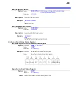
Page 42: ...e RESet SYSTem Execute system reset 32 EXT I O Set and Query Trigger edge Syntax command IO EDGE ON OFF Query IO EDGE Response ON OFF Description Set trigger edge ON PNP fall NPN rise OFF PNP rise NPN fall Example IO EDGE ON Set trigger edge to ON edge IO EDGE ON Trigger edge has been ON edge Set and Query TRIG Signal s Filter Function Syntax command IO FILTer STATe ON OFF Query IO FILTer STATe Re...

Page 43: ...ge monitor check Outputs a high level signal When a fail judgment is given for the contact check or voltage monitor check Outputs a low level signal Example IO GOLogic NORMal Set GO signal outputting logic level to NORMAL IO GOLogic NORMAL GO signal outputting logic level has been set to NORMAL Set and Query EOM Output Method Syntax command IO EOM MODE HOLD PULSe Query IO EOM MODE Response HOLD PU...

Page 44: ...DE NPN NPN PNP Switch has been set to NPN 33 Device Event Status Enable Register Set and Query Device Event Status Enable Register Syntax Command DSE 0 255 NR1 Query DSE Response 0 255 NR1 Example Command Set Device Event status enable register Query Query Device Event status enable register 128 64 32 16 8 4 2 1 bit 7 bit 6 bit 5 bit 4 bit 3 bit 2 bit 1 bit 0 Unused Unused BOV BFL STP ITL LM2 Unus...

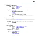
Page 45: ...on or after the RST command this is initialized to OFF no header 35 Communications Settings Return to Local Control Syntax Command SYSTem LOCal Description Disables communications remote control and re enables local control The panel keys are re enabled Example SYSTem LOCal Set Delimiter GP IB Syntax Command SYSTem TERMinator LF CRLF Query SYSTem TERMinator Response LF CRLF Description LF Set deli...

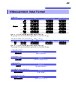
Page 46: ...A sign is returned as a space ASCII code 20H The priority of contact check NG is higher than Current Over Range Resistance Ohm Resistivity OhmRS OhmRV OhmRL Format Range Max Current Over Range Contact check NG UNIT 2mA 20pA 999 999E 000 000E 30 555 555E 30 EXP 2mA 20pA 9 99999E 0 00000E 30 5 55555E 30 Note A sign is returned as a space ASCII code 20H The priority of contact check NG is higher than...

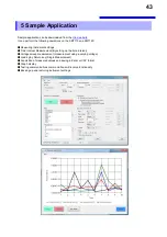
Page 47: ...trument settings Time Interval Measurement By setting up the time interval Voltage sweep measurement measurement using a varying voltage Loading by Return key Single Measurement Acquisition of measured values and saving in Excel or CSV format Graph display Testing communications command transmit receive functionality Backing up and restoring instrument settings ...

Page 48: ... mode setting DSP 0 1 MEASure FORMat UNIT EXP DSP Query response in display mode is same as setting DSP MEASure FORMat DLY Trigger delay time ms setting DLY 0 9999 DELay Delay time s NR2 DLY Query response on trigger delay time is same as setting DLY DELay AVE Averaging setting AVE 0 1 Specifying 1 will cause the auto averaging function to be set Specifying 2 will cause the average hold function t...

Page 49: ...pecifying 1 will cause an external trigger to be set TRIGger INTernal EXTernal TGM Query response of trigger mode is same as setting TGM Because the instrument does Not support the 1 setting the response will be either 0 or 2 TRIGger RDT Measured data query RDT 0 2 MEASure MEASure COMParator MEASure RESult 1 255 CMP Comparison Measuring mode setting CMP 0 1 0 2 9 9999E 30 9 9999E 30 9 9999E 30 9 9...

Page 50: ... 10 NR1 IDN Equipment ID query IDN This query generates a response of Name of manufacturer Name of model Serial number Software IDN CAL Self calibration current range calibration execute CAL Auto calibration takes about 5 sec CALibration TST Self diagNosis result query TST This query returns 0 if there is No error or 1 if there is a ROM error The DSM8104 uses the opposite logic TST TRG The same fu...

Page 51: ......

Reviews: