26
2.6 Diode Check
2.6 Diode Check
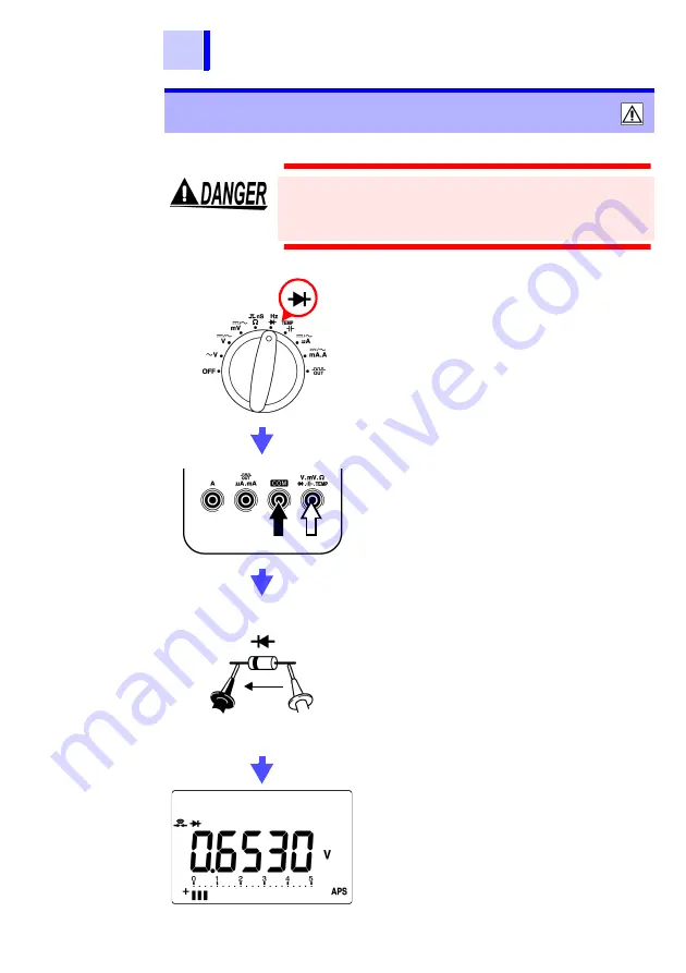
Never apply voltage to the test leads. Doing so may
damage the instrument and result in personal injury.
To avoid electrical accidents, remove power from
the circuit before measuring.
1.
Set the function switch.
2.
Connect the test leads to the test ter-
minals.
3.
Connect the test leads to the object
being tested.
4.
Read the value displayed in the
main display.
With a normal diode, the sequential order
voltage (0.3 to 0.8 V) is displayed.
When the display value less than 0.0500 V,
buzzer sounds.
When the display value drops to the range
of 0.3 to 0.8 V, a single buzzer sounds to in-
dicate that a diode was detected.
However, in relative value display mode,
this conforms with the internally measured
value, not the display value.
<Example>
Red
Black
Sequential
order
Cathode
Anode
Black Red
Summary of Contents for 3801-50
Page 1: ...3801 50 DIGITAL HiTESTER Instruction Manual...
Page 2: ......
Page 40: ...36 2 12 Pulse Output Function...
Page 90: ...86 6 5 Checking the Instrument Software Version...
Page 91: ......
Page 92: ......


