background image

4.6.2

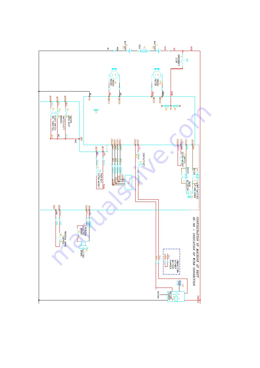
R30SC PLUS

66

Summary of Contents for 108538

Page 1: ...SERVICE MANUAL TRIDENT R30SC R28SC Version AA Date August 5 2019 Document Number 100x...

Page 2: ...4 Frame and traction system what to do if 22 2 5 Solution delivery system what to do if 23 III Functional Groups 24 3 Electrical System 25 3 1 Description 25 3 2 Location of Electrical Components 26...

Page 3: ...3 Work requirements 92 7 4 Operating mode 93 7 5 Related electrical circuit 94 7 6 Adjustments 98 7 7 Disassembly 99 8 Water Unit 101 8 1 Location on machine 101 8 2 Main Components 101 8 3 Work requi...

Page 4: ...Part I Product Introduction 4...

Page 5: ...ollecting during its forward motion the removed dirt and the detergent solution not absorbed by the floor The machine can be powered by single monobloc batteries to provide 24 V DC to the motors and t...

Page 6: ...uickly perform troubleshooting and repair Digital voltmeter DC Current Probe with Full Scale 40 200A Densimeter Hydraulic Lift Charger Serial Data Cable PN 435226 Electronic boards LCD programmer PN 4...

Page 7: ...5 Maximum forward speed Work Default mph 3 5 Maximum backward speed Default mph 2 5 Steering Diameter in 77 Suggested battery Voltage Capacity V AhC5 6 200 Battery compartment dimensions Width Length...

Page 8: ...age Nominal Power V W 24 410 24 600 Vacuum Motor Stages Nr 2 3 Vacuum Motor Depression mbar 118 179 Sound pressure level ISO 11201 LpA dB A 63 70 Technical Data TRIDENT R28SC TECHNICAL DESCRIPTION U M...

Page 9: ...perator lb 1270 1237 TRIDENT TECHNICAL DESCRIPTION U M R30SC R28SC Weight front wheels lb 249 245 Front wheels pressure lb in2 37 33 Weight rear right wheel lb 491 481 Rear right wheel pressure lb in2...

Page 10: ...1 6 Machine Dimensions 1 6 1 R30SC 10...

Page 11: ...1 6 2 R28SC 11...

Page 12: ...s X Check Clean Tanks Hoses X Check Clean the Brushes Pads X Check Clean the Squeegee X Check Clean Recovery Tank Float X Empty Clean Debris Catch Tray of Recovery Tank X Check EACH Battery Cell s Wat...

Page 13: ...y charger 8 Vacuum Group 2 Solution Tank 9 Electrical Harness 3 Side Brush Deck 10 Traction and Frame Group 4 Front Carter Group 11 Squeegee 5 Brush Deck Control 12 Squeegee Control 6 Brush Deck 13 Wa...

Page 14: ...rd and Braking Proceed with on site adjustments brushdeck and Squeegee adjustment Check the functioning of the Optional if present Rear camera Anti collision sensors Front lights Service lights Wand K...

Page 15: ...Part II Anomalies Resolution Guide 15...

Page 16: ...n 2 1 at page 16 6 The machine is powered properly Check the battery charge level and if necessary perform a recharge cycle or replace it The machine has a very limited working autonomy 1 The BDI Batt...

Page 17: ...r wires are damaged Replace the damaged wires 8 The battery charger is not properly adjusted Adjust the battery charger properly see section 3 4 3 at page 46 9 The battery charger doesn t work Check t...

Page 18: ...y mode Press the traction pedal 6 The recovery tank is full Empty the recovery tank completely 7 The brush rotates in opposite way Check the motor connections 8 The microswitch of the traction pedal d...

Page 19: ...he Main Board and replace it if necessary see section at page 8 The brush motor is not working even if powered Check the Float and Recovery Tank and if full drain it completely If the problem persists...

Page 20: ...acuum motor doesn t work properly Refer to the proper section see section 2 3 at page 21 7 The squeegee is lifted up from the floor Lower down the squeegee 8 The squeegee rubber blades are worn out or...

Page 21: ...the electrical wiring and proper operation of the Main Board and replace it if necessary see section at page 8 The vacuum motor is not working even if pow ered Check the Float and Recovery Tank and if...

Page 22: ...he operator must sit on the seat 5 The operator is sitting on the seat Check and or replace the seat see section at page 6 The pedal is not pressed Press the pedal depending on the required speed 7 Th...

Page 23: ...s sary replace it see section at page 8 PLUS HDC The flojet or the peristaltic pump doesn t work Check the pump connections and if necessary replace the non working one 9 The solenoid valve doesn t wo...

Page 24: ...Part III Functional Groups 24...

Page 25: ...card receive as input all the information from the micro switches and all the electronic devices of the machine These signals are translated from the main card to run correctly the scrubber dryer and...

Page 26: ...3 2 Location of Electrical Components 3 2 1 R30SC R28SC Plus 26...

Page 27: ...switch Multimode 22 Seat microswitch 23 Electronic Brake microswitch 24 Full recovery tank Float 26 Rear Left Light 27 Rear Right Light 28 Front Left Light 29 Front Right Light 30 Solenoid Valve 31 Si...

Page 28: ...3 2 3 R30SC Base 28...

Page 29: ...h 23 Electronic Brake microswitch 24 Full recovery tank Float 24A Empty recovery tank Float FLR 24B Empty solution tank Float FLR 25 Recycle Solenoid Valve FLR 26 Rear Left Light 27 Rear Right Light 2...

Page 30: ...ine and depending of the input information decides how to use the devices of the machine during normal work On the table here below is possible to identify the input output signals of the card Card Ca...

Page 31: ...ter 6 Traction pedal micro 16 Yellow Input J4 1 Encoder 31 Green 5V 2 Encoder 31 White 3 Encoder 31 Yellow 5 Work Light 18 Red 12V 6 Encoder 31 Brown Negative J6 2 Position Light 22 Green Negative 3 S...

Page 32: ...cle LED 14 Rose 5 Electrobrake Micro 16 Orange NO 6 Multimode Micro 12 Red NC 7 extra pressure Lever 11 Blue 8 Brushdeck lever Micro 14 White NO 11 Common 11 Red Positive 12 Recycle Full Sensor 27 Lig...

Page 33: ...ck Actuator 21 Light Blue 6 Max pressure Micro 12 Rose Input J12 1 Side brush Actuator 20 Light Blue 2 BTO microswitch Pressure Lev 1 3 BTO microswitch Pressure Lev 3 4 Side brush Actuator 20 Brown 5...

Page 34: ...ing information for the GPS positioning RFID Card Positioned inside the steering column recognizes the badge inserted into the slot and allows the activation of the machine RFID Key The RFID key to be...

Page 35: ...he operating parameters 3 2 11 Key switch The key switch provides the power supply to the whole machine 3 2 12 Extra pressure Lever The lever allows the switch to increase the pressure exerted on the...

Page 36: ...ce lights positioned at key inspection points facilitate the operations especially in dimly lit places 3 2 19 Safety switch Seat The seat safety switch molded into the seat disables the machine functi...

Page 37: ...cked only when the machine is running and pedal pressed It can be unlocked manually 3 2 23 Traction Pedal The traction pedal contains an activation microswitch and a non adjustable electronic potentio...

Page 38: ...s Curve speed reduction Microswitch It is positioned below the platform After a predetermined angle of rotation of the steering the microswitch opens and the curve speed reduction function is activate...

Page 39: ...icro is pressed Vacuum motor Microswitch Base The micro is on the squeegee lifting lever With lowered squeegee lever and closed micro when the traction pedal is pressed the suction motor is activated...

Page 40: ...alues according to the voltage value of the batteries where Vb is the voltage read on the battery Display Vb Pb60 Gel60 Pure Lead Pb80 Gel80 100 24 3 24 3 24 5 24 3 24 3 90 24 3 24 3 24 5 24 3 24 3 80...

Page 41: ...d main board Check the connection between the cards If the problem persists replace the main card or the display card AL 7 General Communication HFM Lack of communication between the BB and the main c...

Page 42: ...Short Circuit Check the connections if the problem per sists replace the main card AL 49 Function Brushes motor 1 Ammeter Overcurrent of the Motor Orbital or Leftside Brush Motor Disc AL 50 Function B...

Page 43: ...rcurrent of the Traction Motor AL 87 Traction Motor data reading Abnormal traction motor Output current Check the traction motor and its connections If the problem persists replace the main card AL 88...

Page 44: ...ot to over tighten in order not to ruin the devices When the setting is finished verify the correct functionality of the microswitches 3 4 2 Hour meter Base Check operation and condition of the hourme...

Page 45: ...er Setting of battery type Voltage DP1 DP2 12 V OFF OFF 24 V OFF ON 36 V ON OFF 48 V ON ON Set Up DP3 DP4 DP5 DP6 Threshold Lead Acid Pb60 OFF OFF OFF OFF 20 2 V OFF OFF OFF ON 20 4 V OFF OFF ON OFF 2...

Page 46: ...hase LED Description A Green Flashes confirms Charge Curve Setting B Red First charging phase C Yellow Second charging phase D Green Charged battery Check if the charger is properly set according to t...

Page 47: ...the yellow LED Error code Flash Description 1 Battery not connected or reverse polarity or output short circuit Verify the battery connection 2 Alarm time out damaged battery or battery capacity is to...

Page 48: ...ammer to the Card on the J2 connector in the position shown in the figure Turn on the machine and operate with the programmer Password 10 Return to the Main Menu and TURN OFF the machine Disconnect th...

Page 49: ...of worked time when the Pedal is pressed KEY HOURMETER hrs min Measure of worked time When the Key is in ON position SERV HOURMETER hrs min Maintenance interval timer TR HOURMETER Measure of worked t...

Page 50: ...the access to basic settings with free access and to the parameter list protected by Password 3222 The structure of the menu can be shown in the following image Turn on the machine and access the menu...

Page 51: ...um function OPT BRUSH MOTOR Access to the parameters of the side brush function ACTUATORS Access to the parameters of the actuators function TRACTION MENU Access to the parameters of the traction func...

Page 52: ...y Custom Level 3 5 V 22 5 15 0 40 0 Valid on Custom Battery Parameter Battery Level 60 General Battery Custom Level 2 5 V 22 0 15 0 40 0 Valid on Custom Battery Parameter Battery Level 40 General Batt...

Page 53: ...ting Parameters Parameter Default Min Max Description General Config Model R30sc Machine Model base plus General Config Base version Brush Machine Version Brush Disc Orbit Orbital General Config Side...

Page 54: ...1 Amp 20 10 40 Sum Pressure Level 1 setting Brush Brush Motor Pressure Level 2 Amp 27 10 40 Sum Pressure Level 2 setting Brush Brush Motor Pressure Level 3 Amp 35 10 40 Sum Pressure Level 3 setting Br...

Page 55: ...Reset Delay sec 300 1 300 When the traction pedal is released the time after which the actuator returns to the rest position From 1 to 299 the parameter is valid only with the value at 300 the actuat...

Page 56: ...ode Time to pass from forward way to reverse way and viceversa Traction Speed Sets Forward Max Speed 100 50 100 Maximum speed in forward way in of the max reachable speed Traction Speed Sets Backward...

Page 57: ...power fuses battery loop wires main card Check periodically the wiring connections status To get access to the electrical system remove the carter under the seat 3 6 2 Batteries Check to perform every...

Page 58: ...sity reading If the measured density is even lower an equalization cycle can be attempted if the charger allows it If in any case the measured density of all or some of the cells is less than the valu...

Page 59: ...ressive degeneration due to corrosion The drop in the electrolyte level is physiological in acid batteries so it is very important to periodically check the electrolyte level and possibly add water if...

Page 60: ...Chapter 4 Washing Unit 4 1 Location on machine The washing unit is located under the machine body in a central position The washing unit control is assembled above it 60...

Page 61: ...uncoupling Knob 11 Brush Deck Body 12 Rightside Brush 13 Brush coupling Flange 14 Brush coupling Spring 15 Leftside Brush 1 Brushdeck support Bushing 2 Brushdeck Actuator 3 Brushdeck support Bushing...

Page 62: ...The batteries are not discharged The operator is seated on the machine so as to press the seat safety switch 1 The machine is on 2 The electrobrake is activated R30SC R28SC PLUS the functions setting...

Page 63: ...d during work Brushdeck Actuator goes down 24V to M4 Brush Motors ON 24V to M2a M2 Solution Pump OFF Solenoid Valve OFF Chemical Pump OFF if available Machine ON Operator Sitting Traction Pedal not pr...

Page 64: ...4 6 Related electrical circuit 4 6 1 R30SC Base 64...

Page 65: ...ed BR2 1 ref to BR2 2 Vb Vb Electrobrake Activated J1 1 ref to J1 2 Vb Vb Traction pedal pressed J3 3 ref to J3 6 Vb Vb Brake pedal pressed J8 5 ref to J8 1 Vb Vb Recovery Tank Floater activated J8 12...

Page 66: ...4 6 2 R30SC PLUS 66...

Page 67: ...vated BR2 1 ref to BR2 2 Vb Vb Electrobrake Activated J1 1 ref to J1 2 Vb Vb Traction pedal pressed J3 3 ref to J3 6 Vb Vb Brake pedal pressed J8 5 ref to J8 1 Vb Vb Recovery Tank Floater activated J8...

Page 68: ...tuator 4 7 Adjustments 4 7 1 Brush Deck The scrub deck is tilted in the transverse direction and should be adjusted longitudinally inclined to the machine so that the brushes have a distance of about...

Page 69: ...om the brush deck actua tor Adjust the brush deck lowering micro blue wire so that there is a maximum distance between the frame and the brush deck mechanics of approx 15 mm Make sure that once the ba...

Page 70: ...ctrical connector of the solenoid valve Disconnect the solution supply hose Remove the seeger that fixes the lifting actuator to the brushdeck Release the traction cross spring Disconnect the lift arm...

Page 71: ...or and switch the machine Off Remove the batteries and the battery support Remove the Front seeger and Pin of the actuator Disconnect the electric wiring of the actuator Remove the Rear seeger and the...

Page 72: ...Chapter 5 Orbital Unit 5 1 Location on machine The sweeping unit is located under the machine body in a central position The sweeping unit control is assembled above it 72...

Page 73: ...rush Bearings 9 Front Brush Motor 10 Brush coupling Pentagon 11 Rear Brush Motor 12 Motor Connector 1 Brush Deck Actuator 2 Sliding bushings 3 Lifting Chain 4 Pressure Control Spring 5 Rotation Bracke...

Page 74: ...teries are not discharged The operator is seated on the machine so as to press the seat safety switch 1 The machine is on 2 The electrobrake is activated 3 The functions setting on the display is Wash...

Page 75: ...d during work Brushdeck Actuator goes down 24V to M4 Brush Motors ON 24V to M2a M2 Solution Pump OFF Solenoid Valve OFF Chemical Pump OFF if available Machine ON Operator Sitting Traction Pedal not pr...

Page 76: ...5 6 Related electrical circuit 5 6 1 R28SC PLUS 76...

Page 77: ...al pressed J3 3 ref to J3 6 Vb Vb Brush Motor Activated J6 8 ref to B Vb Vb Brake pedal pressed J8 5 ref to J8 1 Vb Vb Recovery Tank Floater activated J8 12 ref to J8 1 Vb Vb Front Brush Alarm J8 9 re...

Page 78: ...he preset pressure 5 7 Adjustments 5 7 1 Orbital Brush Deck The scrub deck is tilted in the transverse direction and should be adjusted horizontal so that the pad evenly lean to the ground and perform...

Page 79: ...rews securing the lifting arms from the Brush Deck assembly Disconnect the electrical connector of the Orbital motor Disconnect the electrical connector of the solenoid valve Disconnect the solution s...

Page 80: ...Chapter 6 Vacuum Unit 6 1 Location on machine The vacuum unit is located in central rear position 80...

Page 81: ...12 Actuator coupling Support 13 Pressure Rod counternut 14 Squeegee lower body 15 Squeegee Front Rubber 16 Squeegee Rear Rubber 17 Squeegee Rear blade Lever 18 Rear Rubber Blade 19 Squeegee Support W...

Page 82: ...not discharged The operator is seated on the machine so as to press the seat safety switch 1 The machine is on 2 The electrobrake is activated 3 R30SC R28SC PLUS The functions setting on the display i...

Page 83: ...ng Vacuum Disabled during work Squeegee Actuator rises 24V to M5 Vacuum Motor OFF after 10 seconds at maximum level RECOVERY TANK FLOATER Assumption Action Result Machine ON Operator Sitting Floater e...

Page 84: ...6 6 Related electrical circuit 6 6 1 R28SC Base 84...

Page 85: ...ctivated VAC 1 ref to VAC 2 Vb Vb Electrobrake Activated J1 1 ref to J1 2 Vb Vb Traction pedal pressed J3 3 ref to J3 6 Vb Vb Brake pedal pressed J8 5 ref to J8 1 Vb Vb Recovery Tank Floater activated...

Page 86: ...6 6 2 R30SC R28SC PLUS 86...

Page 87: ...ey Contact Activated J10 1 ref to J10 5 Vb Vb Display Negative J10 4 ref to B Vb Vb Display Transmitting J10 3 ref to B Vb Vb Display Receiving J10 7 ref to B Vb Vb Display Positive J10 8 ref to B Vb...

Page 88: ...loor and vacuum system on The goal of the adjustment is to let the squeegee blade be angled 45 degrees to the floor for its whole length To obtain the correct adjustment act on the squeegee wheels adj...

Page 89: ...uirements Switched Off machine squeegee mounted on the machine Procedure Remove the black plastic cover from the brush deck actua tor Adjust the brush deck lowering micro brown wire so that the squeeg...

Page 90: ...the screw at the side of the pin itself 6 8 2 Squeegee Actuator Lower the squeegee to the floor Put the machine in safe conditions Remove the batteries and the battery support Disconnect the electric...

Page 91: ...Chapter 7 Frame and Traction Unit 7 1 Location on machine The frame and traction unit is located under the machine body 91...

Page 92: ...12 Rear Wheels 13 Front Wheels 14 Touchscreen Display 15 Key Switch 16 Horn 17 Steering Chain 7 3 Work requirements The traction unit only works if the following conditions are met The batteries are...

Page 93: ...ON Operator Sitting Backward function enabled during traction Traction motor ON after 2 seconds 24V to M1 M2 Machine ON Operator Sitting Traction pedal not pressed during transfer Traction motor OFF a...

Page 94: ...7 5 Related electrical circuit 7 5 1 R30SC Base 94...

Page 95: ...Vb Vb Traction pedal pressed J3 3 ref to J3 6 Vb Vb Potentiometer Activated J3 2 ref to J3 4 Vb Vb Potentiometer Signal Activated J3 5 ref to B Vb Vb Encoder activated J4 1 ref to B Vb Vb Encoder act...

Page 96: ...7 5 2 R30SC R28SC PLUS 96...

Page 97: ...Vb Encoder activated J4 3 ref to B Vb Vb Encoder activated J4 6 ref to B Vb Vb Brake pedal pressed J8 5 ref to J8 1 Vb Vb Speed Red microswitch J8 6 ref to J8 1 Vb Vb Seated Operator J8 15 ref to J8 1...

Page 98: ...the sprocket mounted on the front wheel Remove the front Cover Loosen the adjusting screws of the chain tensioner bracket and the screws that fix the lower flange of the steering shaft Once the optim...

Page 99: ...connectors 1 2 7 7 2 Front Wheel Lift up the front wheels from the ground Remove the screw that secures the two wheels to the shaft Remove the shaft being careful to keep the spacers inserted between...

Page 100: ...than the other screws in the assembly Considering that when all eight screws have been removed the gearmotor will be free to fall to the ground Remove the spacers in the gearmotor just uninstalled In...

Page 101: ...ain Components 1 Seat 2 Solution Tank 3 Water Valve adjustment Rod 4 Chemical Pump 5 Water Pump 6 Solution Tank Reserve Floater 7 Water fill Cap 8 Chemical dosing cap 9 Rear Light 10 Solution tank dra...

Page 102: ...e accelerator pedal is pressed 7 8 4 Operating mode WASHING Assumption Action Result Machine ON Operator Sitting Washing Enabled Forward pedal pressed Solenoid Valve ON if water level is different tha...

Page 103: ...sult Machine ON Operator Sitting Recycled button enabled Solution tank reserve floater enabled ref to J8 2 J8 1 Recovery tank reserve floater disabled ref to J8 3 J8 1 Forward pedal pressed Recycle Pu...

Page 104: ...8 5 Related electrical circuit 8 5 1 R30SC Base 104...

Page 105: ...f to J6 5 Vb Vb Side brush Solenoid Valve Activated J6 14 ref to J6 6 Vb Vb Recycle Pump Activated J7 4 ref to J7 4 Vb Vb Empty Solution tank floater activated J8 2 ref to J8 1 Vb Vb Empty Recovery ta...

Page 106: ...8 5 2 R30SC R28SC PLUS 106...

Page 107: ...b Vb Side brush Solenoid Valve Activated J6 14 ref to J6 6 Vb Vb Water Pump Activated J7 3 ref to J7 1 Vb Vb Recycle Pump Activated J7 4 ref to J7 4 Vb Vb Empty Solution tank floater activated J8 2 re...

Page 108: ...oid valve allows a regular flow to the brushes Solenoid Valve The solenoid valve is located on the back of the brush deck body which can be easily accessed from the left side Side Brush Solenoid Valve...

Page 109: ...BRUSH TYNEX 15 ABRASIVE 0 035 Grey 449915 TAMPICO BRUSH 15 NATURAL FIBRE 0 035 Grey 405508 PAD HOLDER 15 Splashguard 447194 RIGHT SPL RUBBER 447193 LEFT SPL RUBBER Carbon Brushes 422462 BRUSH MOTOR CA...

Page 110: ...0 43 x 1 409409 VACUUM M CAR BR PLUS 0 27 x 0 55 x 0 75 9 1 3 Machine Frame and Traction System TRIDENT PN Description Width in R30SC R28SC 442935 ANTISKID FRONT WHEEL 8 86 x 2 36 442936 ANTISKID REA...

Page 111: ...DENT PN Description R30SC R28SC 223301 LEFT GEARMOTOR 24V 500W 140RPM C MOLEX 223444 RIGHT GEARMOTOR 24V 500W 140RPM C MOLEX 219082 BRUSH FLANGE 205990 BRUSH HOLDER PLATE 411738 MOTOR MP80S 2 24V 600W...

Page 112: ...Part IV Accessories and Add On 112...

Page 113: ...he machine in safe condition Switch off the machine and unplug the batteries Before removing the batteries lower the base to the ground 10 2 3 Installing instructions Unplug the power cable of the bat...

Page 114: ...ve of the batteries connected in the emergency button Connect the black wire cable with ring to the negative black cable of the batteries connected in the main card Install the FOB reader in the machi...

Page 115: ...be connected to the battery charger on the data logger connector To do this remove the charger from the machine by unscrewing the two battery charger support screws under the seat The two screws are...

Page 116: ...r cable of the batteries Lift up the related rear wheel from the ground Remove the hub cap Loosen the fixing bolt of the wheel to the drive shaft and remove the wheel Fit the rear wheel Proceed the sa...

Page 117: ...Hillyard Inc Service Manual TRIDENT R30SC R28SC Hillyard Inc 302 North 4th Street P O Box 909 St Joseph Missouri 64501 USA Tel 1 800 365 1555 Fax 1 800 881 3840 Edition August 5 2019...

Reviews: