Storage Enclosure Quick Start Guide
13
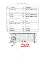
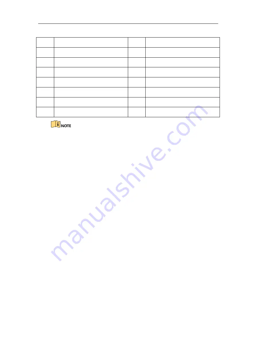
Table 3-2
Panel Description
No.
Description
No.
Description
1
Power module 1
8
Exp (Down)
2
Power module 2
9
Network management port
3
SAS cable connection indicator
10
COM
4
Host (Up1)
11
Fn button
5
Host (Up2)
12
Fn indicator
6
SAS cable connection indicator
13
Power switch
7
SAS cable connection indicator
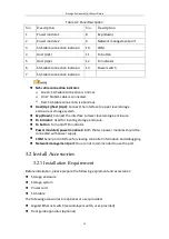
SAS cable connection indicator:
Green: SAS cable connection is normal.
Unlit: No SAS cable is connected.
Red: SAS cable connection is abnormal.
Host (Up1)/host (Up2): Connect the interface to upper level storage
enclosure or storage system.
Exp (Down): Connect the interface to lower level storage enclosure.
Fn indicator: Used for locating storage enclosure.
Fn button: Turn on/off Fn indicator.
Power module 1/power module 2: Both the two power modules should be
connected with power supply.
COM: Serial port interface for viewing controller information and debugging.
Network management port: You are not recommended to use the port.
3.2 Install Accessories
3.2.1 Installation Requirement
Before installation, please prepare the following equipment and accessories:
Storage enclosure
Storage system
Power cord
SAS cable
The following accessories are optional or user-provided:
Gigabit Ethernet switch (second-layer switch, user-provided)
Rack guide apparatus (optional)

