HIKVISION DeepinMind Super iDS-96064NXI-I16 User Manual Download Page 80

Network Video Recorder User Manual   

78 

7.10 Configure Redundant Recording 

Purpose: 

Enabling redundant recording, which means saving the record files not only in the R/W HDD but 
also in the redundant HDD, will effectively enhance the data safety and reliability. . 


You must set the storage mode to Group before you set the HDD property to Redundancy. For 
detailed information, please refer to Chapter 7.2.1 Configure HDD Group. There should be at least 
another HDD which is in Read/Write status. 

Step 1


Go to Storage > Storage Device.     

Step 2


Select a HDD from the list and Click 

  to enter the Local HDD Settings interface. 
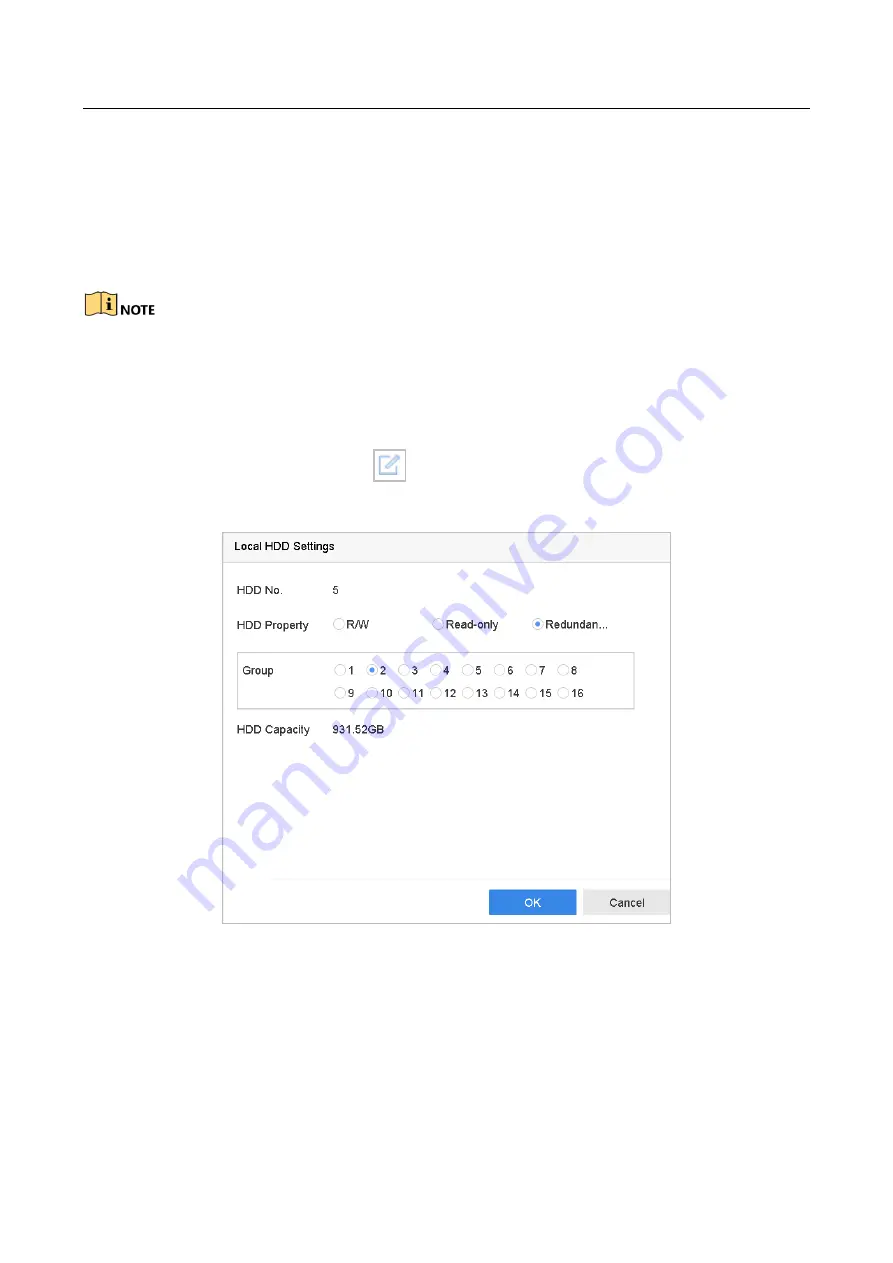
Step 3


Set the HDD property to Redundancy


Figure 7-11


HDD Property-Redundancy 

Step 4


Go to Storage > Schedule Settings > Record Schedule

Step 5


Click Advanced to set the camera recording parameters. 

Summary of Contents for DeepinMind Super iDS-96064NXI-I16

Page 1: ...Network Video Recorder User Manual...

Page 2: ...tioned below are the properties of their respective owners Legal Disclaimer TO THE MAXIMUM EXTENT PERMITTED BY APPLICABLE LAW THE PRODUCT DESCRIBED WITH ITS HARDWARE SOFTWARE AND FIRMWARE IS PROVIDED...

Page 3: ...nce 2 This device must accept any interference received including interference that may cause undesired operation EU Conformity Statement This product and if applicable the supplied accessories too ar...

Page 4: ...ls that may be found in this document are defined as follows Symbol Description Provides additional information to emphasize or supplement important points of the main text Indicates a potentially haz...

Page 5: ...e device turn off the power at once and unplug the power cable and then please contact the service center Preventive and Cautionary Tips Before connecting and operating your device please be advised o...

Page 6: ...g HDMI VGA1 and HDMI2 VGA2 outputs provided HDMI Video output at up to 4K resolution Multiple screen display in live view is supported and the display sequence of channels is adjustable Live view scre...

Page 7: ...and manual recording Searching record files by events alarm input motion detection Tag adding for record files searching and playing back by tags Locking and unlocking record files Local redundant rec...

Page 8: ...matic restore when system is abnormal Other Local Functions Operable by front panel mouse remote control or control keyboard Three level user management admin user is allowed to create many operating...

Page 9: ...operation Remote HDD formatting and program upgrading Remote system restart and shutdown RS 232 RS 485 transparent channel transmission Alarm and exception information can be sent to the remote host...

Page 10: ...in to the Device 28 2 4 1 Log in via Unlock Pattern 28 2 4 2 Log in via Password 29 2 5 Enter Wizard to Configure Quick Basic Settings 29 2 6 Enter Main Menu 33 2 7 System Operation 34 2 7 1 Log out 3...

Page 11: ...iew Layout 48 5 4 Configure Auto Switch of Cameras 50 5 5 Configure Channel Zero Encoding 50 5 6 Main and Auxiliary Ports Strategy 51 5 7 Facial Recognition 51 Chapter 6 PTZ Control 54 6 1 PTZ Control...

Page 12: ...ent Triggered Recording 75 7 8 Configure Alarm Triggered Recording 76 7 9 Configure Holiday Recording 76 7 10 Configure Redundant Recording 78 Chapter 8 Disk Array 80 8 1 Create Disk Array 80 8 1 1 En...

Page 13: ...2 2 Set Play Strategy in Important Custom Mode 100 10 2 3 Edit Video Clips 101 10 2 4 Switch between Main Stream and Sub Stream 101 10 2 5 Thumbnails View 101 10 2 6 Fisheye View 102 10 2 7 Fast View...

Page 14: ...12 7 Unattended Baggage Detection 126 12 8 Object Removal Detection 127 12 9 Audio Exception Detection 128 12 10 Sudden Scene Change Detection 129 12 11 Defocus Detection 130 12 12 PIR Alarm 131 Chap...

Page 15: ...gure TCP IP Settings 149 16 2 Configure DDNS 150 16 3 Configure PPPoE 151 16 4 Configure NTP 151 16 5 Configure SNMP 152 16 6 Configure Email 153 16 7 Configure Ports 155 Chapter 17 Hot Spare Device B...

Page 16: ...r 19 General System Settings 176 19 1 Configure General Settings 176 19 2 Configure Date Time 177 19 3 Configure DST Settings 177 19 4 Manage User Accounts 178 19 4 1 Add a User 178 19 4 2 Set the Per...

Page 17: ...e Solid blue device is on Solid red device is off 3 Mute button Turn on off alarm beep Solid blue Alarm sound is off Unlit Alarm sound is on 4 HDD indicator Solid red at least one HDD is installed Unl...

Page 18: ...blue device is on Solid red device is off 3 LCD 7 inch LCD for live view image and menu operation 4 HDD sequence indicator Shows the HDD sequence 5 Power indicator Flashing blue network transmission i...

Page 19: ...ecific device by changing the Device ID as follows 1 2 1 Pairing Enabling the IR Remote to a Specific Device optional You can pair an IR Remote to a specific device by creating a user defined Device I...

Page 20: ...device functions proceed as follows Press the DEV key on the IR Remote Any existing Device ID will be erased from the unit s memory and it will no longer function with the device Re enabling the IR Re...

Page 21: ...Press Enter button 12 to accept selection If User Is Not Logged On 1 Hold Power On Off button 1 down for five seconds to display the user name password prompt 2 Press the Enter button 12 to display th...

Page 22: ...pper and lower case alphabet symbols and numerals 6 REC Enter Manual Record setting menu Call a PTZ preset by using the numeric buttons in PTZ control settings Turn audio on off in Playback mode 7 PLA...

Page 23: ...led batteries properly in the remote control And you have to aim the remote control at the IR receiver in the front panel If there is no response after you press any button on the remote follow the pr...

Page 24: ...and the polarities of the batteries are not reversed Batteries are fresh and not out of charge IR receiver is not obstructed No fluorescent lamp is used nearby If the remote still can t function prope...

Page 25: ...ur provider The operation of the mouse Table 1 4 Description of the Mouse Control Name Action Description Left Click Single Click Live view Select channel and show the quick set menu Menu Select and e...

Page 26: ...nu 6 USB 3 0 interface Universal Serial Bus USB ports for additional devices such as USB mouse and USB Hard Disk Drive HDD 7 RS 232 Interface Connector for RS 232 devices 8 eSATA Connects external SAT...

Page 27: ...ice gets the power supply Step 2 Press the POWER button on the front panel The Power indicator LED should turn blue indicating that the unit begins to start up Step 3 After startup the Power indicator...

Page 28: ...better protect your product Step 2 In the Create Channel Default Password text field create a login password for IP camera s connected to the device Step 3 Optional Check Export GUID and Security Que...

Page 29: ...After the device is activated you can enter the following interface to configure the device unlock pattern Step 2 Use the mouse to draw a pattern among the 9 dots on the screen Release the mouse when...

Page 30: ...to unlock the device Please configure the pattern first before unlocking Please refer to Chapter 2 3 Configure Unlock Pattern for Login Step 1 Right click the mouse on the screen and select the menu...

Page 31: ...e device before operating the menu and other functions Step 1 Select the User Name in the dropdown list Figure 2 4 Login Interface Step 2 Input password Step 3 Click Login to log in When you forget th...

Page 32: ...up interface Figure 2 5 Date and Time Settings Step 2 After the time settings click Next to enter the Network Setup Wizard window as shown in the following figure Figure 2 6 Network Settings Step 3 Cl...

Page 33: ...terface to add the IP cameras 1 Click Search to search the online IP Camera Before adding the camera make sure the IP camera to be added is in active status 2 Click the Add to add the camera If the ca...

Page 34: ...n password if required Figure 2 10 Change Password You can enter click the to show the characters input 1 Check the checkbox of New Admin Password 2 Enter the original password in the text field of Ad...

Page 35: ...gularly especially in the high security system resetting the password monthly or weekly can better protect your product Step 8 Click OK to complete the startup Setup Wizard 2 6 Enter Main Menu After y...

Page 36: ...if you want to perform any operations you need to enter user name and password log in again Step 1 Click on the menu bar Figure 2 12 Logout Step 2 Click Logout After you have logged out the system men...

Page 37: ...Click the Shutdown button Step 3 Click the Yes button Do not press the POWER button again when the system is shutting down 2 7 3 Reboot the Device From the Shutdown menu you can also reboot the device...

Page 38: ...same password in Create New Password and Confirm New Password Or you can check Use Channel Default Password to activate the camera with channel default password Step 5 Click OK 3 1 2 Add the IP Camer...

Page 39: ...t password Step 5 Click Add to finish the adding of the IP camera Step 6 Optional Click Continue to Add to continue to add other IP cameras 3 1 3 Add the Automatically Searched Online IP Cameras Step...

Page 40: ...the IP camera s firmware upgrade file to the device Step 1 On the camera management interface select a camera Step 2 Go to More Settings Upgrade at the top taskbar Step 3 Select the firmware upgrade f...

Page 41: ...ed Protocols Purpose To connect the network cameras which are not configured with the standard protocols you can configure the customized protocols for them The system provides 16 customized protocols...

Page 42: ...rtsp 192 168 1 55 554 ch1 main av_stream The protocol type and the transfer protocols must be supported by the connected IP camera Result Step 3 After adding the customized protocols you can see the...

Page 43: ...rom the drop down list Step 3 Edit the name in the Camera Name text field Step 4 Check the checkbox of the Display Name Display Date and Display Week if you want to show the information on the image S...

Page 44: ...of Enable to enable this feature Step 4 Use the mouse to draw a zone on the window The zones will be marked with different frame colors Figure 4 2 Privacy Mask Settings Interface Up to 4 privacy mask...

Page 45: ...list Step 3 Select the day night switch mode to Day Night Auto or Auto Switch Auto The camera switches between the day mode and the night mode according to the illumination automatically The sensitivi...

Page 46: ...value results in the brighter image Backlight Set the wide dynamic range 0 to 100 of the camera When the surrounding illumination and the object have larger difference in brightness you should set th...

Page 47: ...starts up or you can click the on the main menu bar to enter the live view interface Step 2 Click to select a window for live view Step 3 Double click the IP camera on the left list to start playing...

Page 48: ...sion view mode 180 Panorama Switch the live view image to the 180 panorama view 360 Panorama Switch the live view image to the 360 panorama view PTZ Expansion The PTZ Expansion is the close up view of...

Page 49: ...ove the position to the center and enable the rectangle area to zoom out 5 1 5 Live View Strategy Step 1 In the live view mode click to enter the digital zoom operation interface in full screen mode S...

Page 50: ...lect the video output to configure Live View Mode Select the display mode for live view Dwell Time The time in seconds to dwell between switching of cameras when enabling auto switch in Live View Enab...

Page 51: ...nd double click on the camera from the list to set the camera to the window You can enter the number in the text field to quickly search the camera from the list You can also click and drag the camera...

Page 52: ...ep 4 Click OK to save the settings 5 5 Configure Channel Zero Encoding Purpose You can enable the channel zero encoding when you need to get a remote view of many channels in real time from web browse...

Page 53: ...n port Aux port You can switch to aux port to do some basic operations like playback switching live view image Third port You can only preview camera image in third port Table 5 1 Main and Auxiliary P...

Page 54: ...ck in toolbar Step 2 Optional Click to select window division Step 3 Select a window as you desired Step 4 Double click a camera from Camera list in the bottom left Step 5 Click Records to view the re...

Page 55: ...o search and export record 1 Set the search parameters as you desired 2 Click Search 3 Click Export Attendance Record or Export Check in Record Ensure you have inserted USB flash drive before export Y...

Page 56: ...Step 1 Click on the quick settings toolbar of the PTZ camera live view The PTZ control wizard pops up as below Figure 6 1 PTZ Control Wizard Step 2 Follow the wizard to adjust the PTZ view focus and...

Page 57: ...ters of the PTZ camera All the parameters should be exactly the same as the PTZ camera parameters Step 4 Click OK to save the settings 6 3 Set PTZ Presets Patrols Patterns Before you start Please make...

Page 58: ...the preset Step 7 Repeat steps 2 6 to save more presets Step 8 Optional Click Cancel to cancel the location information of the preset Step 9 Optional Click in the lower right corner of live view to vi...

Page 59: ...t The key points are corresponding to the presets Step 1 Click on the quick settings toolbar of the PTZ camera live view The PTZ control panel displays on the right of the interface Step 2 Click Patro...

Page 60: ...responding key point 2 Click Apply to save the key points to the patrol Step 6 Optional Click to edit the added key point Figure 6 10 Edit Key Point Step 7 Optional Select a key point and click to del...

Page 61: ...all the pattern to make the PTZ movement according to the predefined path Step 1 Click on the quick settings toolbar of the PTZ camera live view The PTZ control panel displays on the right of the inte...

Page 62: ...k Stop to stop calling it 6 3 7 Set Linear Scan Limits Before you start Please make sure the connected IP camera supports the PTZ function and is properly connected Purpose The linear scan can be enab...

Page 63: ...scan and click it again to stop it Step 3 Optional Click Restore to clear the defined left limit and right limit data Reboot the camera to take the settings into effect 6 3 9 One touch Park Before ope...

Page 64: ...p Park Preset 1 to inactivate it 6 4 Auxiliary Functions Before you start Please make sure the connected IP camera supports the PTZ function and is properly connected Purpose You can operate the auxil...

Page 65: ...Network Video Recorder User Manual 63 Table 6 1 Description of Aux Functions Icons Icon Description Light on off Wiper on off 3D positioning Center...

Page 66: ...ructions 7 1 2 Add the Network Disk You can add the allocated NAS or disk of IP SAN to device and use it as network HDD Up to 8 network disks can be added Add NAS Step 1 Go to Storage Storage Device S...

Page 67: ...NAS disk return to the HDD Information menu The added NetHDD will be displayed in the list Add IP SAN Step 1 Go to Storage Storage Device Step 2 Click Add to enter the Custom Add interface Step 3 Sele...

Page 68: ...select it and click the Init button for initialization 7 1 3 Configure eSATA for Data Storage When there is an external eSATA device connected to device you can configure eSATA for the data storage a...

Page 69: ...eSATA or initialize it is required 7 2 Storage Mode 7 2 1 Configure HDD Group Purpose Multiple HDDs can be managed in groups Video from specified channels can be recorded onto a particular HDD group t...

Page 70: ...ber for the current HDD Step 5 Click OK Regroup the cameras for HDD if the HDD group number is changed Step 6 Go to Storage Storage Mode Step 7 Check the checkbox of Group tab Step 8 Select the group...

Page 71: ...settings 7 2 2 Configure HDD Quota Purpose Each camera can be configured with allocated quota for the storage of recorded files Step 1 Go to Storage Storage Mode Step 2 Check the checkbox of Quota tab...

Page 72: ...y button to apply the settings When the quota capacity is set to 0 all cameras will use the total capacity of HDD for record and picture capture Reboot the device to activate the new storage mode sett...

Page 73: ...and HDD storage space A higher resolution frame rate and bitrate setting will provide you the better video quality but it will also require more internet bandwidth and use more storage space on the h...

Page 74: ...le will be deleted If you set the expired time to 0 the file will not be deleted The actual keeping time for the file should be determined by the capacity of the HDD Redundant Record Capture By enabli...

Page 75: ...types are configurable Continuous scheduled recording Event recording triggered by all event triggered alarm Motion recording triggered by motion detection Alarm recording triggered by alarm M A recor...

Page 76: ...o enable Motion Alarm M A motion or alarm M A motion and alarm and Event triggered recording you must configure the motion detection settings alarm input settings and other events as well Please refer...

Page 77: ...11 2 Configure Alarm Linkage Actions for details Step 3 Go to Camera Encoding Parameters Recording Parameters Step 4 Set the event main stream sub stream recording parameters for the camera Step 5 Go...

Page 78: ...fer to Chapter 11 and Chapter 12 VCA Event Alarm for details Step 3 Go to Camera Encoding Parameters Recording Parameters Step 4 Set the event main stream sub stream recording parameters for the camer...

Page 79: ...oliday Settings 1 Edit the holiday name 2 Select the mode to by date by week or by month 3 Set the start and end date of the holiday 4 Click OK Step 4 Set the schedule for the holiday recording Refer...

Page 80: ...re you set the HDD property to Redundancy For detailed information please refer to Chapter 7 2 1 Configure HDD Group There should be at least another HDD which is in Read Write status Step 1 Go to Sto...

Page 81: ...Network Video Recorder User Manual 79 Figure 7 12 Record Parameters Step 6 Check the checkbox of Redundant Record Capture Step 7 Click OK to save settings...

Page 82: ...evels depending on what level of redundancy and performance is required 8 1 Create Disk Array Purpose The device supports the disk array that is realized by software You can enable the RAID function a...

Page 83: ...e model and capacity Step 1 Go to Storage RAID Setup Physical Disk Figure 8 2 Physical Disk Step 2 Click One touch Config Step 3 Edit the array name in Array Name text filed and click OK to start conf...

Page 84: ...e array Table 8 2 Required Number of HDD RAID Level Required Number of HDD RAID 0 At least 2 HDDs RAID 1 At least 2 HDDs RAID 5 At least 3 HDDs RAID 6 At least 4 HDDs RAID 10 The number of HDD must be...

Page 85: ...ional by array rebuilding 8 2 1 Configure Hot Spare Disk Purpose Hot spare disks are required for disk array automatic rebuilding Step 1 Go to Storage RAID Setup Physical Disk Figure 8 4 Physical Disk...

Page 86: ...start At least one available physical disk should exist for rebuilding the array Step 1 Go to Storage RAID Setup Array Figure 8 6 Array List Step 2 Click of degraded array Figure 8 7 Rebuild Array St...

Page 87: ...ual 85 8 3 Delete Array Deleting array will delete all the data saved in it Step 1 Go to Storage RAID Setup Array Figure 8 8 Array List Step 2 Click of array to delete Figure 8 9 Attention Step 3 Clic...

Page 88: ...it Firmware Purpose You can view the information of the firmware and set the background task speed on the Firmware interface Step 1 Go to Storage RAID Setup Firmware Figure 8 10 Firmware Step 2 Option...

Page 89: ...ance etc Figure 9 1 Search Conditions Step 3 Click Search to display results The matched files are displayed in thumbnail or list Step 4 Select Target Picture or Source Picture in menu bar to display...

Page 90: ...t pictures to backup device 9 2 Search and Export Vehicle Files 9 2 1 Search Vehicle Files Purpose Specify detailed conditions to search vehicle files Before you start Configure vehicle detection func...

Page 91: ...e type Target Picture Display the search results of vehicle close up Source Picture Display the search results of original picture captured by camera Group Sort the search results by selected item 9 2...

Page 92: ...File Management All Files Human File Vehicle File Step 2 Click Show More and set the search conditions Step 3 Click Save Step 4 Enter a name in text field and click Finished The saved search condition...

Page 93: ...e is no recording during the last five minutes Step 1 On the live view window of the selected camera move the cursor to the window bottom to access the toolbar Step 2 Click to start instant playback F...

Page 94: ...channel s to execute simultaneous playback of multiple channels The playing speed of 256X is supported 10 1 3 Video Synopsis Purpose Video synopsis is an approach to create a short video summary of a...

Page 95: ...re and after the time will be played 10 1 4 Play Tag Files Purpose Video tag allows you to record related information like people and location of a certain time point during playback You can use video...

Page 96: ...erface select a tag file and click to start playing the video 10 1 5 Play by Smart Search Purpose In the smart playback mode the device will analyze the video containing the motion line or intrusion d...

Page 97: ...on detection or motion detection event triggered recording Line Crossing Detection 1 Click the icon 2 Click on the image to specify the start point and end point of the line Intrusion Detection 1 Clic...

Page 98: ...stom Search on the left bottom to enter the Search Condition interface Step 3 Enter the search conditions for the event files e g time event type file status vehicle information for vehicle detection...

Page 99: ...the drop down list in the upper left corner of the page to enter the Sub periods Playback interface Step 3 Select a date and start playing the video file Select the Split screen Number from the dropdo...

Page 100: ...h channels after searching system logs Step 1 Go to Maintenance Log Information Step 2 Click Log Search tab to enter Playback by System Logs Step 3 Set search time and type and click Search Figure 10...

Page 101: ...External File Purpose You can play files from the external storage devices Before You Start Connect the storage device with the video files to your device Step 1 Go to Playback Step 2 Click the icon a...

Page 102: ...Custom Mode Purpose When you are in the important or custom video playback mode you can set the playing speed separately for the normal video and the important custom video or you can select to skip t...

Page 103: ...e of the video clipping Export the video clips to the local storage device 10 2 4 Switch between Main Stream and Sub Stream You can switch between the main stream and the sub stream during the playbac...

Page 104: ...Expansion The PTZ Expansion is the close up view of some defined area in the fisheye view or panorama expansion and it supports the electronic PTZ function which is also called e PTZ Radial Expansion...

Page 105: ...1X single camera playback mode 10 2 8 Digital Zoom In the video playback mode click from the toolbar to enter the digital zoom interface You can move the sliding bar or scroll the mouse wheel to zoom...

Page 106: ...tep 3 Optional If you want to copy the same arming schedule of the current day to the other day s of the week or holiday you can click the icon to copy arming schedule settings Step 4 Click Apply to s...

Page 107: ...en the alarm is triggered simultaneously in several channels you must configure the auto switch dwell time Step 1 Go to System Live View General Step 2 Set the event output and dwell time Event Output...

Page 108: ...PC installed with client software e g iVMS 4200 iVMS 5200 Step 1 Go to System Network Advanced More Settings Step 2 Set the alarm host IP and alarm host port Step 3 Go to the Linkage Action interface...

Page 109: ...for the alarm output settings 11 2 6 Configure PTZ Linkage The system can trigger the PTZ actions e g call preset patrol pattern when the alarm event or VCA detection events occur Make sure the PTZ o...

Page 110: ...t the motion detection area Full screen click to set the full screen motion detection for the image Customized area use the mouse to click and drag on the preview screen to draw the customized motion...

Page 111: ...Network Video Recorder User Manual 109 Step 7 Set the linkage actions Refer to Chapter 11 2 Configure Alarm Linkage Actions...

Page 112: ...larm response action s Step 1 Go to System Event Normal Event Video Loss Figure 11 5 Set Video Loss Detection Step 2 Select the camera to configure the video loss detection Step 3 Check Enable Step 4...

Page 113: ...tep 4 Set the video tampering area Use the mouse to click and drag on the preview screen to draw the customized video tampering area You can click Clear to clear the current area settings and draw aga...

Page 114: ...the list and click Figure 11 7 Alarm Input Step 3 Select the alarm input type to N C or N O Step 4 Edit the alarm name Step 5 Check the radio button of Input Step 6 Set the arming schedule Refer to Ch...

Page 115: ...rming Figure 11 8 One Key Alarm Disarming Step 6 Select the alarm linkage action s you want to disarm for the local alarm input1 When the alarm input 1 Local 1 is enabled with one key disarming the ot...

Page 116: ...Manually Clear you should manually clear the alarm when the alarm occurs Refer to Chapter 11 8 Trigger or Clear Alarm Output Manually for detailed instructions Step 5 Set the arming schedule Refer to...

Page 117: ...inkage actions Step 1 Go to System Event Normal Event Exception Step 2 Optional Enable the event hint if you want to display the event hint in the live view window 1 Check the checkbox of Enable Event...

Page 118: ...Network Video Recorder User Manual 116 Figure 11 11 Exceptions Handling Step 4 Set the normal linkage and alarm output triggering Refer to Chapter 10 2 Setting Alarm Linkage Actions...

Page 119: ...ually When the Manually Clear is selected for the dwell time of an alarm output the alarm can be cleared only by clicking Clear button Step 1 Go to System Event Normal Event Alarm Output Step 2 Select...

Page 120: ...s must be supported by the connected IP camera Refer to the User Manual of Network Camera for the detailed instructions for the VCA detection 12 1 Face Detection Purpose Face detection function detect...

Page 121: ...Detection Purpose Vehicle Detection is available for the road traffic monitoring In Vehicle Detection the passed vehicle can be detected and the picture of its license plate can be captured You can se...

Page 122: ...p 10 12 3 Line Crossing Detection Purpose Line crossing detection detects people vehicles and objects crossing a set virtual line The detection direction can be set as bidirectional from left to right...

Page 123: ...e Sensitivity slider to set the detection sensitivity Sensitivity range sensitivity The higher the value is the more easily the detection alarm can be triggered 4 Click Draw Region and set two points...

Page 124: ...e of the object loitering in the region When the duration of the object in the defined detection area is longer than the threshold device will trigger an alarm Its range is 1s 10s Sensitivity The size...

Page 125: ...p 11 Click Apply 12 5 Region Entrance Detection Purpose Region entrance detection function detects objects that enter a pre defined virtual region from the outside place Step 1 Go to System Management...

Page 126: ...a quadrilateral in the preview window by specifying four vertexes of the detection region Step 8 Draw the maximum size minimum size for targets Only target the size of which is rangers from max size a...

Page 127: ...configure Up to 4 regions are selectable 2 Drag the sliders to set Sensitivity Sensitivity The higher the value is the more easily the detection alarm can be triggered Its range is 0 100 3 Click Draw...

Page 128: ...nattended Baggage Detection Step 3 Select a Camera to configure Step 4 Check Enable Unattended Baggage Detection Step 5 Optionally check Save VCA Picture to save the captured pictures of unattended ba...

Page 129: ...re Alarm Linkage Actions Step 9 Click Apply 12 8 Object Removal Detection Purpose Object removal detection function detects the objects removed from the pre defined region such as the exhibits on disp...

Page 130: ...from the region can trigger the alarm 3 Click Draw Region and draw a quadrilateral in the preview window by specifying four vertexes of the detection region Step 7 Set the arming schedule Refer to Ch...

Page 131: ...the change should be to trigger the detection Range 1 100 Sound Intensity Threshold It can filter the sound in the environment The louder the environment sound the higher the value should be Adjust i...

Page 132: ...vity slider to set the detection sensitivity Sensitivity range 1 100 The higher the value is the more easily the change of scene can trigger the alarm Step 7 Set the arming schedule Refer to Chapter 1...

Page 133: ...he value is the more easily the defocus image can be detected Step 7 Set the arming schedule Refer to Chapter 11 1 Configure Arming Schedule Step 8 Set the linkage actions Refer to Chapter 11 2 Config...

Page 134: ...ure Step 4 Check PIR Alarm Step 5 Optionally check Save VCA Picture to save the captured pictures of PIR alarm Step 6 Set the arming schedule Refer to Chapter 11 1 Configure Arming Schedule Step 7 Set...

Page 135: ...an Body Picture Recognition Vehicle or Number of People Exception Detection Step 3 If an engine usage is set as Video Structuralization Real Time or Video Structuralization Video select the Video Stru...

Page 136: ...eras to enable corresponding analysis mode Ensure engine is available for the selected analysis mode Step 3 Enable auto analysis 1 Click Edit 2 Optionally check Enable of Display Status and Notify Sur...

Page 137: ...ehicle Search Step 2 Select the IP camera for the vehicle search Step 3 Set search conditions Figure 13 3 Human Body Search Step 4 Click Start Search 13 4 People Counting Purpose The feature is used t...

Page 138: ...eople visited and stayed in a specified area The heat map function must be supported by the connected IP camera and the corresponding configuration must be set Step 1 Go to Smart Analysis Heat Map Ste...

Page 139: ...ual 137 As shown in the figure above red color block 255 0 0 indicates the most visited area and blue color block 0 0 255 indicates the less popular area Step 6 Optional Click Export to export the sta...

Page 140: ...rt Analysis Engine Configuration to select at least one engine as Video Structuralization Real Time Step 4 Enabling the function will change smart events supported by the camera Step 5 Select the came...

Page 141: ...ge actions Refer to Chapter 11 2 Configure Alarm Linkage Actions Step 11 Click Apply to activate the settings 14 2 Enable Human Body Smart Analysis Step 1 Go to Smart Analysis Smart Analysis Engine Co...

Page 142: ...t Import human body pictures you want to search Step 1 Go to Smart Analysis Smart Search Human Body Detection Search by Appearance Figure 14 2 Search by Appearance Step 2 Specify search conditions Ste...

Page 143: ...of uploaded human body picture will be listed 14 3 2 Search by Picture Purpose Upload several pictures of one person to compare with captured human body pictures thus to increase search accuracy Befo...

Page 144: ...ch results will be arranged in similarity ascending order 14 3 3 Add Search Result as Sample Picture Purpose You can add searched human body pictures as sample pictures And then search human body pict...

Page 145: ...son with the live captured face picture 15 1 1 Add a Face Picture Library Step 1 Go to Smart Analysis Face Picture Database Step 2 Click Step 3 Enter library name and click OK Figure 15 1 Add Face Pic...

Page 146: ...mport Related Operations Select pictures and click Copy to to copy the uploaded pictures of the current library to other library Select a picture and click Edit to modify the picture information Selec...

Page 147: ...on produced a match both the real time face picture and the target picture from the library will be uploaded If no match is produced the real time face picture is uploaded to center only Up to 6 conne...

Page 148: ...igure Alarm Linkage Actions Step 10 Click Apply to save the settings 15 3 2 Configure Stranger Alarm Purpose Compare detected human face with specified face picture library Trigger alarm when comparis...

Page 149: ...t in Linkage Action interface Step 7 Select face picture libraries and set similarity Step 8 Set the arming schedule Refer to Chapter 11 1 Configure Arming Schedule Step 9 Set the linkage actions Refe...

Page 150: ...y personal name Step 1 Go to Smart Analysis Smart Search Face Search Search by Name Step 2 Set the start time and end time of the face pictures to search Step 3 Select IP channel Step 4 Enter Name to...

Page 151: ...e same IP address and you can select the main NIC to LAN1 or LAN2 By this way in case of one NIC card failure the device will automatically enable the other standby NIC card so as to ensure the normal...

Page 152: ...e You Start You must register DynDNS PeanutHull and NO IP services with your ISP before configuring DDNS settings Step 1 Go to System Network TCP IP DDNS Step 2 Check Enable Step 3 Select DynDNS under...

Page 153: ...you need to configure user name and password accordingly under System Network TCP IP PPPoE Contact your Internet service provider for details about PPPoE service 16 4 Configure NTP Purpose Connection...

Page 154: ...NTP server NTP Port Port of the NTP server Step 4 Click Apply 16 5 Configure SNMP Purpose You can configure SNMP settings to get device status and parameter information Before You Start Download the S...

Page 155: ...y 16 6 Configure Email Purpose The system can be configured to send an Email notification to all designated users when a specified event occur such as an alarm or motion event is detected or the admin...

Page 156: ...The SMTP port The default TCP IP port used for SMTP is 25 Enable SSL TLS Check to enable SSL TLS if required by the SMTP server Sender The name of the sender Sender s Address Sender s Address Select...

Page 157: ...ort configured in the software Server Port Server port 8000 by default should be configured for remote client software access and its valid range is 2000 to 65535 HTTP Port HTTP port 80 by default sho...

Page 158: ...Network Video Recorder User Manual 156 Figure 16 6 Port Settings...

Page 159: ...nal connection shown in the figure below is required to be built between the hot spare device and each working device Set a hot spare device Add a hot spare device on normal device Add the normal devi...

Page 160: ...on afterwards 17 3 Set Working Device Step 1 Go to System Hot Spare Step 2 Set the Work Mode as Normal Mode Step 3 Check Enable Step 4 Enter the IP address and admin password of hot spare device Figur...

Page 161: ...device gets offline the hot spare device will record the video of the IP camera connected to the working device for backup The record backing up can be functioned for 1 working device at a time Synch...

Page 162: ...lect the HDDs to clone to eSATA HDD Before you start Connect an eSATA disk to the device Step 1 Go to Maintenance HDD Operation HDD Clone Figure 18 1 HDD Clone Step 2 Check the HDD to clone The capaci...

Page 163: ...a monitoring system for HDD to detect and report on various indicators of reliability in the hopes of anticipating failures Step 1 Go to Maintenance HDD Operation S M A R T Step 2 Select the HDD to v...

Page 164: ...he checkbox of the Continue to use the disk when self evaluation is failed item 18 1 3 Bad Sector Detection Step 1 Go to Maintenance HDD Operation Bad Sector Detection Step 2 Select the HDD No in the...

Page 165: ...see the detailed damage information 18 1 4 HDD Health Detection Purpose You can view the health status of Seagate HDD that generated after October 1th 2017 and capacity ranges from 4 TB to 8 TB The f...

Page 166: ...ep 2 Click a HDD to view details 18 2 Search Export Log Files Purpose The operation alarm exception and information of the device can be stored in log files which can be viewed and exported at any tim...

Page 167: ...al 165 Figure 18 6 Log Search Interface Step 2 Set the log search conditions including the Time Major Type and Minor Type Step 3 Click Search to start search log files The matched log files will be di...

Page 168: ...d information Click the button to view the related video file 18 2 2 Export the Log Files Before You Start Connect a storage device to your device Step 1 Search the log files Refer to Chapter 18 2 1 S...

Page 169: ...e Format button to format the storage device before log export 18 3 Import Export IP Camera Configuration Files Purpose The information of added IP camera can be generated into an excel file and expor...

Page 170: ...ars Step 3 Export or import the IP camera configuration files Click Export to export configuration files to the selected local backup device To import a configuration file select the file from the sel...

Page 171: ...e storage device must be with the file Before You Start Connect a storage device to your device For importing the configuration file the storage device must be with the file Step 1 Go to Maintenance I...

Page 172: ...rade interface Figure 18 10 Local Upgrade Interface Step 3 Select the update file from the storage device Step 4 Click Upgrade to start upgrading Step 5 After the upgrading is complete the device will...

Page 173: ...al 171 Figure 18 11 FTP Upgrade Interface Step 3 Enter the FTP Server Address in the text field Step 4 Click the Upgrade button to start upgrading Step 5 After the upgrading is complete reboot the dev...

Page 174: ...fault route server port etc and user account parameters to the factory default settings Factory Defaults Restore all parameters to the factory default settings Restore to Inactive Restore the device t...

Page 175: ...e selectable digest and digest basic For security reasons it is recommended to select digest as the authentication type Disable HTTP Purpose The admin user account can disable the HTTP service from th...

Page 176: ...IP Camera Occupation Detection Purpose After enabling the feature when search IP camera in Number of Unadded Online Device interface the status of IP camera the has been added by other device will sho...

Page 177: ...name and enter the strong password Step 5 Select the user level to Media User Operator and Admin Step 6 Click OK to save the settings Result The added user accounts have the permission to connect oth...

Page 178: ...ttings Interface Step 2 Configure the following settings Language The default language used is English Output Standard Select the output standard to NTSC or PAL which must be the same with the video i...

Page 179: ...tton to save the settings 19 2 Configure Date Time Step 1 Go to System General Step 2 Configure the date and time Time Zone Select the time zone Date Format Select the date format System Date Select t...

Page 180: ...2 00 a m on the second Sunday of March and ends at 2 00 a m on the first Sunday of November with 60 minutes ahead Step 4 Click the Apply button to save the settings 19 4 Manage User Accounts Purpose...

Page 181: ...resetting the password monthly or weekly can better protect your product User Level Set the user level to Operator or Guest Different user levels have different operating permission Operator The Opera...

Page 182: ...ons including the local and remote operation for the device Step 1 Go to System User Step 2 Select a user from the list and then click the button to enter the permission settings interface Figure 19 7...

Page 183: ...izing two way radio between the remote client and the device Remote Alarm Control Remotely arming notify alarm and exception message to the remote client and controlling the alarm output Remote Advanc...

Page 184: ...user Step 3 Enter admin password and click OK Step 4 Select cameras that non admin user can view in local and click OK Figure 19 8 Enable Live View Permission Step 5 Click of non admin user Step 6 Ent...

Page 185: ...password strong password is required and MAC address Step 4 Edit the unlock pattern for the admin user account 9 Check the checkbox of Enable Unlock Pattern to enable the use of unlock pattern when lo...

Page 186: ...Step 6 Click the OK button to save the settings Step 7 For the Operator or Guest user account you can also click the button on the user management interface to edit the permission 19 4 5 Edit the Oper...

Page 187: ...ion as demand including the new password strong password is required and MAC address 19 4 6 Delete a User The admin user account has the permission to delete the operator guest user account Step 1 Go...

Page 188: ...alization applications Search human body by appearance or by similarity search vehicle by appearance Video structuralization 4 ch real time video structuralization 16 ch historical video structuraliza...

Page 189: ...t panel 2 USB 2 0 Rear panel 2 USB 3 0 Front panel 1 USB 2 0 Rear panel 2 USB 3 0 Alarm in out 16 8 Extension board Slot 2 3 Extension board Not supported 1 4 RJ 45 10 100 1000 Mbps self adaptive opti...

Page 190: ...ive DNS configuration of its configured hostnames addresses or other information stored in DNS PPPoE Stands for Point to Point Protocol over Ethernet PPPoE is a network configuration used for establis...

Page 191: ...g if the output mode of device is HDMI output then the input mode of monitor must be the HDMI input And if not please modify the input mode of monitor Step 7 Check if the fault is solved by the step...

Page 192: ...e device and IP camera lost connections The configured parameters are incorrect when adding the IP camera Insufficient bandwidth Step 1 Verify the network is connected 1 Connect the device and PC with...

Page 193: ...to check if the PC connects with the IP camera Step 3 Verify the network between IP camera and device is stable 3 When the IP camera is offline connect PC and device with the RS 232 cable 4 Open the S...

Page 194: ...mera orders and window division modes can be set for different output interfaces separately and digits like D1 and D2 stands for the channel number and X means the selected window has no image output...

Page 195: ...en image is stuck connect the RS 232 ports on PC and the rear panel of device with the RS 232 cable 2 Open the Super Terminal and execute the command of ping 192 168 0 0 l 1472 f the IP address may ch...

Page 196: ...e volume is too low Possible Reasons Cable between the pickup and IP camera is not connected well impedance mismatches or incompatible The stream type is not set as Video Audio The encoding standard i...

Page 197: ...of 720p the frame extracting may occur which leads to a slight stuck Step 5 Verify the network between device and IP camera is connected 1 When image is stuck connect the RS 232 ports on PC and the r...

Page 198: ...tem time setting is correct Go to Menu System General and verify the Device Time is correct Step 2 Verify the search condition is correct Go to playback interface and verify the channel and time are c...

Page 199: ...Network Video Recorder User Manual 197 UD10737B...

Reviews: