63
CDR-830
7. GENERAL INFORMATION
7.1 DIAGNOSIS
7.1.1 ERROR CODE
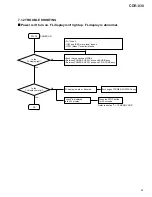
Error Code Display for Service
The CDR-830 can display the error codes for service.
When the STOP key is held down for about 10 seconds in stop
state in Normal mode, an FL display as shown below is obtained.
Right 2 FL digits : Error code for service
The error code for service is displayed as a number (ERROR
NUMBER), which follows a message "CHECK DISC" or
"CHECK." For details, see the table below.
Display
Error code table for service
Error code Number(2 digits)
999999
∗∗
Code
Symptom
Contents of Error
Possible Cause
Checkpoints
L
∗
The unit stops during the
tray open/close operation.
(CHECK display)
Improper loading
• Defective tray position sensor
• Defective loading motor
• Improper soldering
• Pattern short
• Improper power supply
IC451 (BA5810FP)
E
∗
The unit stops when PLAY
or REC/PAUSE starts.
(CHECK display)
Defective slider
• The pickup cannot be returned to the
specified position.
• Disconnected flexible cable
• Defective drive circuit
• Abnormal power supply
• Abnormal TOC position switch
• Improper soldering
S601 (PSG1014)
IC451 (BA5810FP)
IC401 (CXD2585Q)
P
∗
The unit does not read the
inserted disc, and stops.
(CHECK DISC display)
Defect in spindle
• Disc upside-down.
• Dirty or cracked disc
• Abnormal disc rotation
• No signal obtained from the disc
C
∗
The unit stops before it
enters REC/PAUSE mode.
Defects related to the recording laser
power
• Dirty or cracked disc
• The optimum recording power
cannot be obtained.
• Trouble in RF detection.
• Defective laser diode
• Trouble in RF detection
• Defective RFT RFB circuit
• Recording power is not sufficient.
• Improper soldering, pattern short
• Trouble with power supply
• Unable to read ATIP or subcode
IC201 (PA9007A)
IC101 (AK8567)
IC308 (TC7S14F)
F
∗
The unit stops during
playback or recording.
Defective pickup
• Unable to focus because of dirt or
crack on the inserted disc.
• Unable to output the proper laser
power
• Defective laser diode
• Defective focus drive circuits
• Defective pickup
• Improper soldering
• Pattern short
• Trouble of power supply
IC451 (BA5810FP)
IC401 (CXD2585Q)
A
∗
The unit stops in a
recording-related operation,
displaying "CHECK DISC."
If any hardware trouble occurs before
displaying A
∗
or d
∗
, the unit stops
displaying a code other than these
codes. Therefore, these service
codes are generated only for troubles
with the disc.
d
∗
The unit stops in a recording
related operation, displaying
"CHECK DISC."
The unit does not read the
inserted disc, and stops.
No.
Mechanism Mode
No.
Mechanism Mode
No.
Mechanism Mode
0
PLAY
5
SETUP
A
REC
1
OPEN
6
TOC READ
B
TOC REC
2
STOP
7
−
C
OPC
3
−
8
SEARCH
D
TOC CHECK
4
−
9
REC/PAUSE
E
PMA, ACTUAL PAUSE REC
The indication for * shows themechanism mode listed below.
• Defective spindle motor
• Defective spindle drive circuit
• Abnormal FG signals
• Defective WBL circuit
• Defective decoder circuit
• Unable to read ATIP or subcode
• High error rate
PC651
(NJL5809K-F1)
IC451 (BA5810FP)
IC401 (CXD2585Q)
• Unable to focus
Stop during recording
• The unit stops, being obstructed by a
dirt or a crack on the disc.
Summary of Contents for BurnIT CDR-830
Page 45: ...CDR 830 45 A B C D 5 6 7 8 5 6 7 8 G IC701 IC702 IC706 CN601 D SIDE A SIDE B...
Page 71: ...71 CDR 830 Pin Function 2 5...
Page 72: ...72 CDR 830 Pin Function 3 5...
Page 73: ...73 CDR 830 Pin Function 4 5...
Page 74: ...74 CDR 830 Pin Function 5 5...
Page 78: ...78 CDR 830 AK8567 CD R CORE PCB ASSY IC101 RF Processor Pin Function 1 2...
Page 79: ...79 CDR 830 Pin Function 2 2...
Page 82: ...82 CDR 830 1 FL TUBE Grid Assignment Pin Connection PEL1101 OPERATING ASSY V701 7 2 2 DISPLAY...
Page 83: ...83 CDR 830 Anode Connection...
Page 89: ...CDR 830 89 ORDER NO RRV2408M T ZZR DEC 2000 Printed in Japan...


