background image

70

CDR-830

7.2 PARTS

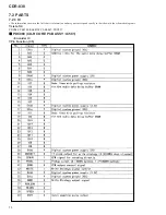
• The information shown in the list is basic information and may not correspond exactly to that shown in the schematic diagrams.

 PDC069 (CD-R CORE PCB ASSY : IC501)

     • Encorder IC

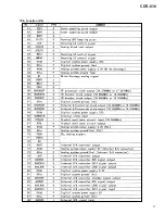
Pin Function (1/5)

7.2.1 IC

List of IC

PDC069, PE5190, BA5810FP, AK8567, PDC077

Summary of Contents for BurnIT CDR-830

Page 1: ...RO CD TEXT PROFESSIONAL CDR 830 FOR U S MODELS NECESSARY INFORMATION FOR DHHS RULES MARKED ON THE REAR BASE AND ON THE TOP OF CD MECHANISM AS BELOW DANGER LASER RADIATION WHEN OPEN AVOID DIRECT EXPOSU...

Page 2: ...ten not evident from visual inspection nor the protection afforded by them necessarily can be obtained by using replacement components rated for voltage wattage etc Replacement parts which have these...

Page 3: ...63 7 1 1 ERROR CODE 63 CONTENTS 7 1 2 TROUBLE SHOOTING 65 7 1 3 ERROR MEESAGE CHECK TEMP 67 7 1 4 DISASSEMBLY 68 7 1 5 DISAGNOSIS OF CD R CORE ASSY 69 7 2 PARTS 70 7 2 1 IC 70 7 2 2 DISPLAY 82 8 PANE...

Page 4: ...when replacing be sure to use parts of identical designation Screws adjacent to mark on the product are used for disassembly WYXJ Type only ENT ER CUR SOR ME NU DEL ETE NA ME MA RK SE T CLE AR DISP LA...

Page 5: ...l Unit PWW1173 NSP 12 Dry Cell Battery R6P AA VEM 013 13 Polyethylene Bag Z21 038 0 03 230 340 14 Packing Case PHG2431 15 Protecter L PHA1349 16 Protecter R PHA1350 17 Packing Sheet AHG7015 18 Battery...

Page 6: ...21 7 39 4 2 6 27 26 10 24 29 15 8 15 38 21 5 21 41 19 21 20 12 9 9 12 16 8 8 31 32 21 32 32 18 21 9 30 9 36 35 13 17 20 Refer to 2 4 CD R CORE ASSY 1 2 2 5 CD R CORE ASSY 2 2 KUXJ CA type only 33 Ref...

Page 7: ...PNA2566 PNA2565 14 Shield Plate Mtl PNB1631 Not used NSP 18 Caution Label PRW1516 Not used 26 Caution Label HE Not used PRW1233 27 Caution Label Not used VRW1094 35 Lami tight 3x6 PBA1116 Not used 36...

Page 8: ...0 PAC2032 12 13 Display Window 830 PAM1833 14 LED Lens Abs PNW2745 15 Front Panel PNW2996 16 17 Sub Panel Abs PNW2975 18 Jog Knob D5 08 PAC1939 24Screw With Washer ABA1005 25 19P Flexible Cable 60v PD...

Page 9: ...B Assy VWG2171 2 32P Flexible Cable 30V PDD1222 3 Connector Assy PG03KK E07 4 DC Motor LOADING PXM1027 5 Connector Assy 2P VKP2253 6 Motor Pulley PNW1634 7 Loading Motor Assy VXX2505 8 Clamper Plate V...

Page 10: ...able on top takes about 9kg pressure Take off the spacer Spacer Spacer OK NG A 2 1 2 8mm 11mm Disc table Assy Pressure of about 9kg Carriage Base PCB Stopper Spindle motor Spacer setting Position Spac...

Page 11: ...eet PNM1325 8 Float Base PNW2964 9 Pinion Gear PNW2994 10 Gear A PNW2855 11 Gear B PNW2856 12 Gear C PNW2969 13 Rack PNW2965 14 Rack Stopper PNW2966 NSP 15 Disc Table PNW2860 16 Carriage Base PNW2967...

Page 12: ...3 8688MHz 24 25 18 19 17 26 20 23 29 32 30 31 29 32 30 15 48 89 43 65 39 41 50 31 24 25 18 19 17 26 20 B C D E F G H FCS FCS FCS TRK TRK FG SPDL 23 A B C D 10 88 31 52 19 TE TE Address Data RFDC RFDC...

Page 13: ...CU04AF L602 OUTPUT L ch R ch AUDIO ASSY D VR ASSY F OPERATING ASSY G POWER SUPPLAY UNIT H 85 86 ADDATA ADBCK ADDATA DAMCK DIN3 DIN1 DITOUT DIN1 DOUT DIN3 13 11 1 1 7 7 3 3 5 5 DALRCK LRCK DADATA DABCK...

Page 14: ...G1072 AC Inlet CN 101 PKP1012 Earth Lead PDF1198 CD R CORE PCB ASSY PWM2339 A CD R CORE ASSY PXA1636 MECHA PCB ASSY PWX1625 C POWER SUPPLY UNIT PWR1029 H CN901 CN602 CN302 CN202 CN901 CN401 CN502 CN20...

Page 15: ...efer to EXPLODED VIEWS and PARTS LIST or PCB PARTS LIST OPERATING ASSY KUZJ CA PWZ4110 WYXJ PWZ4112 G HEADPHONE ASSY KUXJ CA PWZ4120 WYXJ PWZ4122 E AUDIO ASSY KUXJ CA PWZ4100 WYXJ PWZ4102 D VOLUME ASS...

Page 16: ...CDR 830 16 A B C D 1 2 3 4 1 2 3 4 3 3 CD R CORE PCB ASSY 1 5 1 5 A 2 2 1 2 BR93LC66F RESET THERMO SENSOR EEPROM CD R CORE PCB ASSY PWM2339 A 1 5 A 4 5 A 3 5...

Page 17: ...R 830 17 A B C D 5 6 7 8 5 6 7 8 1 5 A PE5190D MECHA CONTROL MICROCOMPUTER 8 BIT LATCH NC The power supply is shown with the marked box A 5 5 A 3 5 A 2 5 A 2 5 4 5 D 2 2 CN602 CN302 3 5 4 1 6 10 9 8 7...

Page 18: ...CDR 830 18 A B C D 1 2 3 4 1 2 3 4 2 5 A 3 4 CD R CORE PCB ASSY 2 5 A 3 5 A 1 5 A 4 5 A 1 5 R R CN101 CN1 CD R CORE PCB ASSY PWM2339 CD R PICKUP PEA1356 A 2 5 11 12 R R...

Page 19: ...CDR 830 19 A B C D 5 6 7 8 5 6 7 8 2 5 A 2 2 F rank 1 F rank 1 2 2 1 2 1 2 A 3 5 A 1 5 A 4 5 A 5 5 A 3 5 A 1 5 A 4 5 CN102 TP_POINT RF PROCESSOR RF SIGNAL ROUTE AUDIO SIGNAL ROUTE REC 14 13 15 16 17 R...

Page 20: ...CDR 830 20 A B C D 1 2 3 4 1 2 3 4 3 5 A 3 5 CD R CORE PCB ASSY 3 5 2 2 2 2 2 2 2 2 1 2 1 2 1 2 1 2 CD R CORE PCB ASSY PWM2339 A 3 5 A 2 5 A 5 5 A 2 5 18...

Page 21: ...CDR 830 21 A B C D 5 6 7 8 5 6 7 8 3 5 A NC NC NC NC NC NC NC SERVO AMP MULTI PLEXER A 1 5 A 2 5 A 4 5 A 4 5 A 1 5...

Page 22: ...CDR 830 22 A B C D 1 2 3 4 1 2 3 4 4 5 A 3 6 CD R CORE PCB ASSY 4 5 EFM ENCODER 4M DRAM NC A 1 5 A 5 5 A 5 5 A 1 5 OP OP 23...

Page 23: ...8 5 6 7 8 4 5 A CD R CORE PCB ASSY PWM2339 A 4 5 A 3 5 A 5 5 D 1 2 CN401 A 2 5 A 5 5 A 2 5 A 2 5 A 3 5 R D OP D OP D D R R R D D D AUDIO SIGNAL ROUTE REC AUDIO SIGNAL ROUTE DIGITAL AUDIO SIGNAL ROUTE...

Page 24: ...4 5 A 2 5 CD R CORE PCB ASSY PWM2339 A 5 5 MECHA PCB ASSY PWX1625 C LOAB ASSY VWG2171 B PC651 NJL5809K F1 CARRIAGE MOTOR ASSY SLIDER PEA1359 DC MOTOR ASSY SPINDLE PXM1044 J601 CN601 CN101 S601 S101 L...

Page 25: ...CDR 830 25 A B C D 5 6 7 8 5 6 7 8 5 5 A A 1 5 A 2 5 A 1 5 A 4 5 The power supply is shown with the marked box CN901 CN202 H SIGNAL ROUTE RF SIGNAL AUDIO SIGNAL DIGITAL D D D 28 F rank 1...

Page 26: ...less than 23 minutes Outer Absolute time is more than 23 minutes W CLV WOBBLECLV E CLV EFMCLV at DIGITAL LOCK at DIGITAL UNLOCK DIRERR IC501 pin 142 0V 5V at MUTE ON Audio Signal Not Output at MUTE O...

Page 27: ...01 pin 37 REWLDON V 200mV div H 1msec div REC RW 20 IC501 pin 38 WLDON V 200mV div H 1msec div REC 21 IC501 pin 45 ODON V 200mV div H 200nsec div REC 22 IC501 pin 48 WDAT V 200mV div H 200nsec div REC...

Page 28: ...40 AUDIO ASSY KUXJ CA PWZ4100 WYXJ PWZ4102 D 1 2 D 2 2 D 2 2 A 4 5 CN401 D 2 2 CN201 CN502 H The power supply is shown with the marked box CN901 KUXJ CA type only SIGNAL ROUTE AUDIO SIGNAL OPTICAL SIG...

Page 29: ...CDR 830 29 A B C D 5 6 7 8 5 6 7 8 1 2 D E CN410 CN402 D 2 2 D 2 2 HEADPHONE ASSY KUXJ CA PWZ4120 WYXJ PWZ4122 E BA4560F...

Page 30: ...KUXJ CA PWZ4100 WYXJ PWZ4102 D 2 2 VOLUME ASSY KUXJ CA PWZ4130 WYXJ PWZ4132 F CN801 CN807 COAX OUT COAX IN Short Point Solder OPT OUT OPT IN OPT IN LINE IN Lch LINE IN Rch OP OP OP CO CO OP OP OP CO C...

Page 31: ...5 6 7 8 5 6 7 8 2 2 D CN601 CN602 D 1 2 A 1 5 CN701 CN302 G The power supply is shown with the marked box SIGNAL ROUTE AUDIO SIGNAL AUDIO SIGNAL REC OPTICAL SIGNAL COAXI AL SIGNAL OP R CO OP OP OP OP...

Page 32: ...RAB4C223J 22k x 4 DISPLAY TITLE MODE S702 S703 S704 SYNCHRO S705 S706 S707 TEXT S708 MENU DELETE S709 OPEN CLOSE S710 RECORD S711 REC MUTE S712 SCROLL S713 DISPLAY S714 TITLE MODE S715 MONITER S716 E...

Page 33: ...CDR 830 33 A B C D 5 6 7 8 5 6 7 8 G The power supply is shown with the marked box D 2 2 CN601 OPERATING ASSY KUXJ CA PWZ4110 WYXJ PWZ4112 G CN701...

Page 34: ...NOTE FOR FUSE REPLACEMENT FOR CONTINUED PROTECTION AGAINST RISK OF FIRE REPLACE WITH SAME TYPE NO 215002 MFD BY LITTELFUSE INC FOR FU1 CAUTION CAUTION FOR CONTINUED PROTECTION AGAINST RISK OF FIRE RE...

Page 35: ...UED PROTECTION AGAINST RISK OF FIRE REPLACE WITH SAME TYPE NO 49101 6 MFD BY LITTELFUSE INC FOR IC1 IC2 and IC4 marked parts Only these parts are supplied as service parts No FU1 Service Parts IC01 IC...

Page 36: ...n this PCB include all necessary parts for several destinations For further information for respective destinations be sure to check with the schematic diagram 4 View point of PCB diagrams Symbol In P...

Page 37: ...830 37 A B C D 1 2 3 4 1 2 3 4 C B 4 1 LOAB and MECHA PCB ASSYS M M CARRIAGE MOTOR SPINDLE MOTOR MECHA PCB ASSY C MECHA PCB ASSY C LOAB ASSY B A CN451 A CN452 PNP1476 A PNP1476 A VNP1762 A SIDE A SID...

Page 38: ...3 4 A 4 2 CD R CORE PCB ASSY PNP1477 B IC307 IC308 IC306 IC309 IC255 IC161 IC305 IC421 IC304 IC422 IC401 IC201 IC931 IC506 Q203 Q204 Q101 IC502 IC107 IC504 IC507 IC303 IC102 IC103 LOADING MOTOR CD R C...

Page 39: ...B C D 1 2 3 4 1 2 3 4 A SIDE B PNP1477 B IC207 IC206 IC251 IC301 Q402 Q201 Q202 Q401 IC253 IC252 IC451 IC101 IC310 IC501 IC503 Q502 IC254 CN101 B CN401 D CN602 D To CD R PICKUP CN601 C CN201 H CD R CO...

Page 40: ...CDR 830 40 A B C D 1 2 3 4 1 2 3 4 4 3 AUDIO HEADPHONE and VOLUME ASSYS PNP1478 A PNP1478 A AUDIO ASSY D VOLUME ASSY F HEADPHONE ASSY E A CN701 G CN502 A D E F SIDE A...

Page 41: ...CDR 830 41 A B C D 5 6 7 8 5 6 7 8 PNP1478 A CN302 A CN201 H Q407 Q408 Q401 Q402 IC902 IC901 IC903 Q409 Q410 SIDE A D...

Page 42: ...CDR 830 42 A B C D 1 2 3 4 1 2 3 4 PNP1478 A IC404 Q405 Q404 Q403 IC801 IC405 IC601 AUDIO ASSY D SIDE B D...

Page 43: ...CDR 830 43 A B C D 5 6 7 8 5 6 7 8 PNP1478 A PNP1478 A IC803 IC804 IC401 Q404 Q403 IC403 IC402 VOLUME ASSY F HEADPHONE ASSY E F E D SIDE B...

Page 44: ...CDR 830 44 A B C D 1 2 3 4 1 2 3 4 4 4 OPERATING ASSY G PNP1478 A PNP1478 A OPERATING ASSY G OPERATING ASSY G Q702 Q701 Q712 Q713 SIDE A SIDE B...

Page 45: ...CDR 830 45 A B C D 5 6 7 8 5 6 7 8 G IC701 IC702 IC706 CN601 D SIDE A SIDE B...

Page 46: ...5 PCB PARTS LIST NOTES Parts marked by NSP are generally unavailable because they are not in our Master Spare Parts List The mark found on some component parts indicates the importance of the safety f...

Page 47: ...EV220M6R3 C581 C582 CEV220M6R3 C281 CEV2R2M50 C101 C127 C130 C401 C409 CEV470M6R3 C452 CEV470M6R3 C108 C232 C258 C543 CKSQYB105K10 C114 C117 C123 C133 C215 CKSQYB334K16 C227 C229 CKSQYB334K16 C426 CKS...

Page 48: ...03 L805 L901 L9447 L9448 OTL1040 L602 PTL1003 CAPACITORS C626 C821 C823 CCSQCH101J50 C807 C808 CCSQCH271J50 C607 CCSQCH470J50 C839 CCSQCH471J50 C834 C838 CEAT100M50 C602 C612 C616 C618 CEAT101M10 C832...

Page 49: ...OTHERS CN701 FFC CONNECTOR 19P 9604S 19C REMOTE RECEIVER UNIT GP1U27X V701 FL TUBE PEL1101 HEADPHONE ASSY COILS AND FILTERS L451 L453 QTL1015 CAPACITORS C458 C459 CCSQCH102J50 C451 CKCYF473Z50 C452 C4...

Page 50: ...ISCS TO BE USED 6 2 MEASURING INSTRUMENTS 6 3 TEST MODE SERVO SYSTEM ADJUSTMENT 6 3 1 How to Enter the Test Mode CD Test disc for adjustment STD 903 or equivalent Test disc for inspection STD 914 or e...

Page 51: ...djustment Points 6 6 LD Power adjustment 6 7 Servo Adjustment Automatic Adjustment 6 7 Servo Adjustment Automatic Adjustment EXCHANGE CD R CORE PCB ASSY Mechanical point Electric point CDR CORE PCB AS...

Page 52: ...r adjustment end Turn off the LD and disc selection set to CD 3 6 PLAY PAUSE Store the power adjustment value to the EEPROM and shift to the next power adjustment 4 RECORD LD POWER adjustment standby...

Page 53: ...ial state is the coarse adjustment 7 Press the PLAY PAUSE key to register the adjustment if the power became the adjustment value assume the power when it was decided by A value When it is registered...

Page 54: ...r the adjustment if the power became the adjustment value 12 Press the STOP key to goes out the LD and adjustment is completed 6 6 3 CD RW Record Power Adjustment RW Bias 2 3 mW 0 05 mW RW Rec 3 2 mW...

Page 55: ...voltage of focus error amplifier Focus in does not function or bad RF wave shape CN102 pin 8 Focus err Test Point Adjustment Value Purpose Symptom when Out of Adjustment Adjustment method FL Indicati...

Page 56: ...Purpose Symptom when Out of Adjustment Adjustment method FL Indication CN102 RF VC 2 6 10 1 prove Oscilloscope Procedure 1 Press the AUTO MANUAL key and shift to the MPP Offset Adjustment 2 Monitor t...

Page 57: ...the AUTO MANUAL key and shift to the Tracking Gain MS MIX Adjustment 2 Move the Pickup to center of the disc by pressing the SCAN key 1 3 Monitor the MPX signal and set a CD disc 4 Press the FINALIZE...

Page 58: ...m in the readjustment 3 Adjust the JOG key so that TE offset becomes zero 4 Press the ENTER key to register the adjustment 6 7 8 MPP Offset Readjustment 0 mV 50 mV CN102 pin 5 Tracking err Test Point...

Page 59: ...ROM 11 Press the STOP key to stop the unit Caution In this adjustment shift to the RFDC Adjustment when pressing the ENTER key before step 9 and there is it when completed in normal on the indication...

Page 60: ...omatic Adjustment Start Method FL Indication Procedure 1 Move the Pickup to center of the disc by pressing the SCAN key 1 2 Monitor the MPX signal with VC and set a CD disc 3 Press the FINALIZE key to...

Page 61: ...n the indication However must not omit operation of steps 5 from 3 because RFDC is not adjusted to normal when pressing the ENTER key with the state that steps 5 from 3 are not executed How to execute...

Page 62: ...ay appears in about 4 sec like C1 Specification 65 pieces or less Press STOP key to reset display 3 Recording playback ATIP error Method While pushing MENU DELETE key press TITLE MODE key Display appe...

Page 63: ...acked disc The optimum recording power cannot be obtained Trouble in RF detection Defective laser diode Trouble in RF detection Defective RFT RFB circuit Recording power is not sufficient Improper sol...

Page 64: ...msec the operation halts P When Q data is not read in 1 sec and ATIP data is not read in 1 sec the system tries to read them for 3 times And when even then both Q data and ATIP data are not read the o...

Page 65: ...No POWER ON FU1 fuse it IC02 and IC03 micro fuse fuses it IC701 Mode Controller breaks Check the connection of PCBs Between POWER SUPPLY assy and AUDIO assy Between POWER SUPPLY assy and CD R CORE ass...

Page 66: ...er Mechanism communication beginning Setting of audio format Mechanism communication Input selection setting Key reception EEPROM communication IC701 PDC077 98 pin EEP DATA IC701 PDC077 100 pin EEP CL...

Page 67: ...sensor which is placed inside of the product becomes 70 or higher or 15 or lower the message is displayed Once this is displayed all the actions stop In addition the product itself has its own temper...

Page 68: ...l 7 2 5 4 9 2 9 2 3 3 2 Unhook 1 2 2 6 2 6 2 2 2 Diagnosis of CD R CORE Assy Servo Mechanism Block Drive Gear Front 4 Rear view CN901 CN502 CN302 CD R CORE Assy 10 5 6 8 7 9 7 CD R CORE Assy Bridge Tr...

Page 69: ...Assy 25P FFC PDD1227 4 3 CN302 CN602 AUDIO Assy 9P FFC PDD1226 5 CN101 CN1 Pickup 32P FFC PDD1224 6 CN451 CN101 LOAB Assy Connector Assy 3P PG03KK 50 1 7 CD R CORE PCB Assy Other Assys 7 1 5 DIAGNOSIS...

Page 70: ...tion shown in the list is basic information and may not correspond exactly to that shown in the schematic diagrams PDC069 CD R CORE PCB ASSY IC501 Encorder IC Pin Function 1 5 7 2 1 IC List of IC PDC0...

Page 71: ...71 CDR 830 Pin Function 2 5...

Page 72: ...72 CDR 830 Pin Function 3 5...

Page 73: ...73 CDR 830 Pin Function 4 5...

Page 74: ...74 CDR 830 Pin Function 5 5...

Page 75: ...u p t u o g n i s r e v e r W R D C 1 2 Q R D L H T I A W X 6 6 P C E D K O L C O d n a m m o c Q 5 8 5 2 D X C r o f t u p t u o K C O L C 2 2 R W X 5 6 P R W X O y r o m e m l a n r e t x e e h t f...

Page 76: ...a r e p m e T 0 6 4 I N A 4 7 P B F R A I t u p n i e p o l e v n e e d i s r e w o l F R k c a b y a l P 1 6 5 I N A 5 7 P T F R A I t u p n i e p o l e v n e t r a p r e p p u F R k c a b y a l P 2...

Page 77: ...1 H C f o t u p n I 9 1 D N G l a n i m r e t D N G e t a r t s b u S 6 2 N I 2 H C f o t u p n I 0 2 4 3 C C V W O P 4 H C 3 H C l a n i m r e t t u p n i y l p p u s r e w o p 7 C C V E R P t u p n...

Page 78: ...78 CDR 830 AK8567 CD R CORE PCB ASSY IC101 RF Processor Pin Function 1 2...

Page 79: ...79 CDR 830 Pin Function 2 2...

Page 80: ...u j d A V 5 y l l a u s u V 0 e d o m t s e T 3 1 C N O 4 1 S S V D N G 5 1 1 F C z H M 0 1 m u l u d n e p e r u t r a p e d c i m a r e C 6 1 2 F C m u l u d n e p e r u t r a p e d c i m a r e C 7...

Page 81: ...i w s l e d o m e h t s i e r e h T 2 9 O T A G E L I k n i l o t a g e l H s i t I h c t i w s l e d o m e h t s i e r e h T 3 9 O M E D I n o i t a r t s n o m e d H s i t I h c t i w s l e d o m e...

Page 82: ...82 CDR 830 1 FL TUBE Grid Assignment Pin Connection PEL1101 OPERATING ASSY V701 7 2 2 DISPLAY...

Page 83: ...83 CDR 830 Anode Connection...

Page 84: ...o monitor the selected input and display digital source information Indicator lights up to remind you when you are monitor ing 6 OPEN CLOSE 0 Press to open or close the disc tray 7 RECORD Press to ent...

Page 85: ...cursor back and forth across character display while using CD text 18 6 Press to play pause or resume playing a disc Also use to start recording from record pause mode and to start finalization and e...

Page 86: ...up when manual track numbering is on during recording 13 SKIP ON Lights up to indicate that a disc contains skip IDs When setting or clearing skip IDs the word SKIP blinks 14 PGM Lights up when progra...

Page 87: ...fade out during playback or recording 15 SKIP PLAY Press to switch skip play on and off 16 SKIP ID SET Instructs the player to skip a particular track on playback 17 SKIP ID CLEAR Clears the above se...

Page 88: ...ayback Signal to noise ratio 108 dB Dynamic range 98 dB Total Harmonic Distortion 1 kHz 0 0023 Channel Separation 98 dB Recording analog input Signal to noise ratio 92 dB Dynamic range 92 dB Total Har...

Page 89: ...CDR 830 89 ORDER NO RRV2408M T ZZR DEC 2000 Printed in Japan...

Page 90: ...l sales hhb co uk HHBCommunicationsUSAInc 743CochranStreet BuildingsE F Simi Valley CA93065 1976 Phone 8055796490 Fax 8055798028 e mail sales hhbusa com HHB Communications Canada 260 King Street East...

Reviews: