background image

To replace the component, reverse the removal procedure.

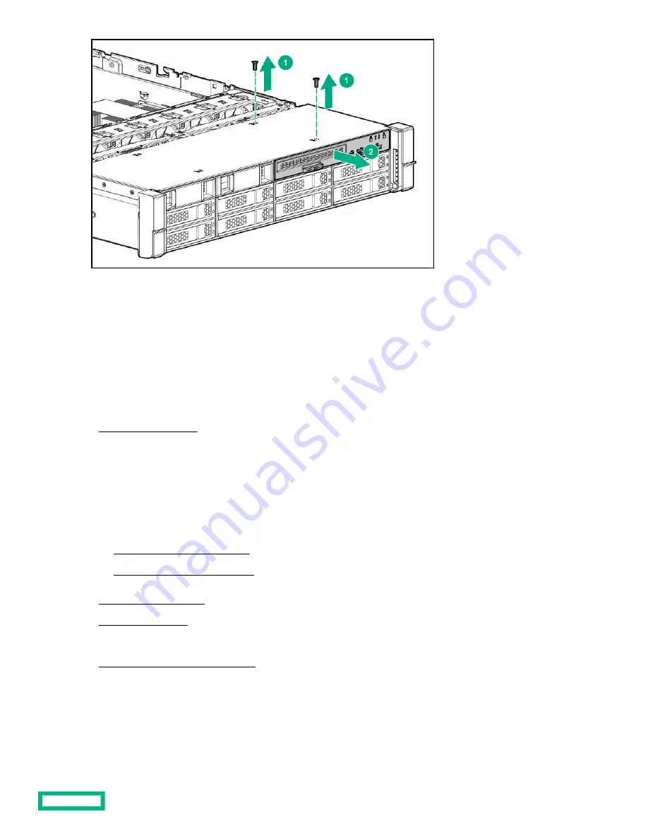
Removing and replacing the SFF optical drive

Prerequisites

Before you perform this procedure, make sure that you have a T-10 Torx screwdriver available.

Procedure

1.

Power down the server.

2.

Remove all power:

a. Disconnect each power cord from the power source.

b. Disconnect each power cord from the server.

3.

Do one of the following:

Extend the server from the rack.

Remove the server from the rack.

4.

Remove the access panel.

5.

Remove the fan cage.

6.

Disconnect all cables from the SFF universal media bay.

7.

Remove the SFF universal media bay.

8.

Remove the optical drive.

Removal and replacement procedures

64

Summary of Contents for HPE ProLiant DL385 Gen10 Plus

Page 1: ...ptember 2020 Edition 4 Abstract This document is for the person who installs administers and troubleshoots servers and storage systems Hewlett Packard Enterprise assumes you are qualified in the servi...

Page 2: ...Software Documentation and Technical Data for Commercial Items are licensed to the U S Government under vendor s standard commercial license Links to third party websites take you outside the Hewlett...

Page 3: ...m board spare parts 17 LFF front I O board spare part 17 Systems Insight Display spare part 17 System battery spare part 17 Server options 17 Drive spare parts 18 Fan spare parts 24 Drive backplane bo...

Page 4: ...ng the OCP NIC 3 0 adapter 61 Removing and replacing the SFF universal media bay 62 Removing and replacing the LFF power switch module 63 Removing and replacing the SFF optical drive 64 Removing and r...

Page 5: ...roubleshooting resources 114 Diagnostic tools 115 Product QuickSpecs 115 UEFI System Utilities 115 Selecting the boot mode 115 Secure Boot 116 Launching the Embedded UEFI Shell 116 Intelligent Provisi...

Page 6: ...le routing Front 8 LFF to system board 160 Cable routing 12 LFF drive options midtray to system board 160 Cable routing Front 12 LFF drive options midtray to HPE Smart Array P816i a SR Gen10 Controlle...

Page 7: ...0W Flex Slot 48VDC Hot plug Low Halogen Power Supply 173 HPE 1600W Flex Slot Platinum Hot plug Low Halogen Power Supply 175 Websites 176 Support and other resources 177 Accessing Hewlett Packard Enter...

Page 8: ...Item Description 1 Air baffle spare part 2 Access panel spare parts 3 Secondary and tertiary PCI riser cage spare part 4 Primary PCI riser cage spare part 5 Chassis ear spare parts 6 Fan cage spare pa...

Page 9: ...part Customer self repair optional Description Spare part number Secondary and tertiary PCI riser cage P24030 001 Primary PCI riser cage spare part Customer self repair mandatory Description Spare pa...

Page 10: ...le management arm P24100 001 DIMM guard spare part Customer self repair mandatory Description Spare part number 2U DIMM guard left right P24307 001 Miscellaneous mechanical spare parts Miscellaneous f...

Page 11: ...tory Description Spare part number Fan blanks 2 Energy pack latch Retention clips for the primary riser cage 2 Retention clip for the secondary tertiary riser cage 875066 001 Optical drive blank spare...

Page 12: ...pare parts 8 System board spare parts 9 LFF front I O board spare part 10 Systems Insight Display spare part 11 System battery spare part Not shown For more information see Removal and replacement pro...

Page 13: ...AA L P20505 001 256 GB 8Rx4 PC4 3200AA L 3DS P20506 001 Processor spare parts AMD EPYC 7xx2 processor spare parts Customer self repair optional Description Spare part number 2 00 GHz AMD EPYC 7702 pro...

Page 14: ...48VDC Hot plug Power Supply 866728 001 HPE 800 W Flex Slot Platinum Hot plug Low Halogen Power Supply 866730 001 HPE 800 W Hot plug Power Supply 866793 001 HPE 1600 W Flex Slot Platinum Hot plug Low...

Page 15: ...Ethernet 1Gb 4 port BaseT I350 T4 adapter P22200 001 HPE Ethernet 10Gb 2 port SFP QL41132 adapter P22199 001 HPE Ethernet 10Gb 4 port SFP QL41134 adapter P13346 001 HPE Ethernet 10Gb 2 port BaseT QL41...

Page 16: ...ged Network Adapter 767078 001 HPE StoreFabric CN1200E T 10Gb Converged Network Adapter 827607 001 OCP NIC 3 0 spare parts Customer self repair optional Description Spare part number HPE 1GbE 4 port B...

Page 17: ...Customer self repair optional Description Spare part number LFF front I O board 875088 001 Systems Insight Display spare part Customer self repair optional Description Spare part number Systems Insigh...

Page 18: ...b SAS Expander Card spare part 8 Energy pack spare parts 9 Power module spare parts 10 HPE NS204i p Gen10 Boot Device spare parts 11 Pensando Distributed Services Platform card spare parts 12 Flex bay...

Page 19: ...881507 001 LFF HDD spare parts 1 TB SATA 7 2K LFF LP DS HDD 862130 001 2 TB SAS 7 2K LFF LP DS HDD 834133 001 2 TB SATA 7 2K LFF LP DS HDD 862132 001 4 TB SAS 7 2K LFF LP DS HDD 834134 001 4 TB SATA 7...

Page 20: ...FF SCN DS SSD P10653 001 1 92 TB NVMe x4 RI SFF SCN DS SSD P10466 001 1 92 TB NVMe Perf MU SFF SC U 3 SSD P20735 001 2 TB NVMe x4 RI SFF SCN DS SSD P13838 001 3 2 TB NVMe x4 MU SFF SCN DS SSD P13828 0...

Page 21: ...1 800 GB SAS MU SFF SC SSD P20838 001 800 GB SAS MU SFF SC SSD P22581 001 800 GB SAS WI SFF SC DS SSD P06602 001 800 GB SAS WI SFF SC DS SSD P09948 001 800 GB SAS WI SFF SC SSD P22586 001 960 GB SAS M...

Page 22: ...001 6 4 TB SAS MU SFF SC DS SSD P06583 001 6 4 TB SAS MU SFF SC DS SSD P09926 001 6 4 TB SAS MU SFF SC SSD P20841 001 6 4 TB SAS MU SFF SC SSD P22584 001 6 4 TB SAS RI SFF SC DS SSD P06599 001 7 68 T...

Page 23: ...U SFF SC DS SSD P08692 001 960 GB SATA MU SFF SC DS SSD P09909 001 960 GB SATA MU SFF SC MV SSD P18478 001 960 GB SATA MU SFF SC SSD P21089 001 960 GB SATA MU LFF LPC SSD P21093 001 960 GB SATA RI SFF...

Page 24: ...MV SSD P18485 001 3 84 TB SATA RI SFF SC SSD P21084 001 3 84 TB SATA RI SFF SC MV SSD P05315 001 3 84 TB SATA VRO SFF SC SSD P25240 001 3 84 TB SATA VRO LFF LPC SSD P25241 001 7 68 TB SATA RI SFF SC M...

Page 25: ...plane 12Gbs 878543 001 8 SFF U 3 backplane premium P24047 001 LFF drive backplane spares 2 LFF backplane stack riser P24042 001 4 LFF SAS backplane P23681 001 Chassis Intrusion Detection Switch spare...

Page 26: ...elf repair optional Description Spare part number HPE DL38x Gen10 Plus 12Gb SAS Expander Card 876907 001 Energy pack spare parts Customer self repair mandatory Description Spare part number HPE Smart...

Page 27: ...FF drive cage SATA drive backplane board Power cable 275 mm SATA HDD cable 430 mm 775428 001 Midtray drive cage spare part Customer self repair optional Description Spare part number 8 SFF NVMe and SA...

Page 28: ...4 8 LFF Box 1 2 to x8 Slim SAS Slim SAS SATA x4 8 LFF Box 3 midtray to x8 Slim SAS Slim SAS to 7p SAS SATA 2 SFF front x4 to 7p SAS SATA 2 SFF front rear P24553 001 NVMe cable spare parts Customer sel...

Page 29: ...emium ports 1 2 to 1A 1B box 2 or 1B 2B box 1 on system board Box 2 premium port 3 4 to 1B 2B on system board Box 2 premium port 3 to Smart Array controller 7A Box 2 premium port 4 to system board 8A...

Page 30: ...FF Re timer PCIe card P27685 001 Split midtray port 1 4 to x32 P24136 001 SAS 1 3 SAS SATA x8 SlimSAS P24137 001 OCP NIC 3 0 cables Slim SAS x8 to low profile Slim SAS x8 Low profile Slim SAS x8 to x8...

Page 31: ...ective part back to Hewlett Packard Enterprise within a defined period of time normally five 5 business days The defective part must be returned with the associated documentation in the provided shipp...

Page 32: ...identifica il guasto come riparabile mediante un ricambio CSR Hewlett Packard Enterprise lo spedir direttamente al cliente per la sostituzione Vi sono due categorie di parti CSR Obbligatorie Parti ch...

Page 33: ...lefon helfen lassen Den Materialien von Hewlett Packard Enterprise die mit einem CSR Ersatzteil geliefert werden k nnen Sie entnehmen ob das defekte Teil an Hewlett Packard Enterprise zur ckgeschickt...

Page 34: ...mpresa de transporte que se utilice para dicho servicio Para obtener m s informaci n acerca del programa de Reparaciones del propio cliente de Hewlett Packard Enterprise p ngase en contacto con su pro...

Page 35: ...a Hewlett Packard Enterprise ou fornecedores parceiros da Hewlett Packard Enterprise concluir que o reparo pode ser efetuado pelo uso de uma pe a CSR a Hewlett Packard Enterprise enviar a pe a direta...

Page 36: ...os termos do servi o de garantia apenas para pe as a Hewlett Packard Enterprise fornece as pe as de reposi o sem cobrar nenhuma taxa No caso desse servi o a substitui o de pe as CSR obrigat ria Se des...

Page 37: ...Customer self repair 37...

Page 38: ...Customer self repair 38...

Page 39: ...Customer self repair 39...

Page 40: ...rs until they arrive at static free workstations Place parts on a grounded surface before removing them from their containers Avoid touching pins leads or circuitry Always be properly grounded when to...

Page 41: ...s and cautions WARNING This server is heavy To reduce the risk of personal injury or damage to the equipment Observe local occupational health and safety requirements and guidelines for manual materia...

Page 42: ...tension peut subsister dans la batterie durant 1 160 secondes CAUTION Protect the server from power fluctuations and temporary interruptions with a regulating uninterruptible power supply This device...

Page 43: ...s method forces the server to enter standby mode without properly exiting applications and the OS If an application stops responding you can use this method to force a shutdown Use a virtual power but...

Page 44: ...the following Procedure 1 Power down the server 2 Extend the server from the rack 3 Disconnect the cabling and remove the server from the rack For more information see the documentation that ships wi...

Page 45: ...lost CAUTION For proper cooling do not operate the server without the access panel baffles expansion slot covers or blanks installed If the server supports hot plug components minimize the amount of...

Page 46: ...4 Remove the access panel 5 Remove the air baffle 6 Release the full length expansion board retainer To replace the component reverse the removal procedure Removing and replacing the rack rails WARNI...

Page 47: ...of the rail first 5 Remove the rail from the rack To replace the component reverse the removal procedure Removing and replacing the cable management arm WARNING To reduce the risk of personal injury o...

Page 48: ...bles from the cable management arm 5 Remove the cable management arm To replace the component reverse the removal procedure Removing and replacing a drive blank CAUTION To prevent improper cooling and...

Page 49: ...on the drive 2 Determine the status of the drive from the drive LED definitions For more information see SAS SATA drive components and LEDs 3 Remove the drive To replace the component reverse the remo...

Page 50: ...ate the server for long periods with the access panel open or removed Operating the server in this manner results in improper airflow and improper cooling that can lead to thermal damage IMPORTANT For...

Page 51: ...the server unless all bays are populated with either a component or a blank Procedure 1 Power down the server 2 Remove all power a Disconnect each power cord from the power source b Disconnect each po...

Page 52: ...down the server 2 Remove all power a Disconnect each power cord from the power source b Disconnect each power cord from the server 3 Disconnect any external cables that are connected to the expansion...

Page 53: ...down the server 2 Remove all power a Disconnect each power cord from the power source b Disconnect each power cord from the server 3 Disconnect any external cables that are connected to the expansion...

Page 54: ...installed Prerequisites Before you perform this procedure make sure that you have a T 10 Torx screwdriver available Procedure 1 Power down the server 2 Remove all power a Disconnect each power cord fr...

Page 55: ...l procedure Removing and replacing the PCIe riser board Prerequisites Before you perform this procedure make sure that you have a T 15 Torx screwdriver available Procedure 1 Power down the server 2 Re...

Page 56: ...the rack 4 Remove the access panel 5 Release the full length expansion board retainer 6 Remove the PCIe riser cage Remove the primary PCIe riser cages Remove the secondary and tertiary PCIe riser cage...

Page 57: ...ut the access panel baffles expansion slot covers or blanks installed If the server supports hot plug components minimize the amount of time the access panel is open Procedure 1 Power down the server...

Page 58: ...er cord from the power source b Disconnect each power cord from the server 3 Disconnect any external cables that are connected to the expansion board 4 Do one of the following Extend the server from t...

Page 59: ...expansion slot cover or an expansion board installed Procedure 1 Power down the server 2 Remove all power a Disconnect each power cord from the power source b Disconnect each power cord from the serve...

Page 60: ...d replacing the fan cage Procedure 1 Power down the server 2 Remove all power a Disconnect each power cord from the power source b Disconnect each power cord from the server 3 Do one of the following...

Page 61: ...d replacing the OCP NIC 3 0 adapter WARNING To reduce the risk of personal injury electric shock or damage to the equipment remove power from the server by removing the power cord The front panel Powe...

Page 62: ...replacing the SFF universal media bay Prerequisites Before you perform this procedure make sure that you have a T 15 Torx screwdriver available Procedure 1 Power down the server 2 Remove all power a...

Page 63: ...the server 2 Remove all power a Disconnect each power cord from the power source b Disconnect each power cord from the server 3 Do one of the following Extend the server from the rack Remove the serv...

Page 64: ...wn the server 2 Remove all power a Disconnect each power cord from the power source b Disconnect each power cord from the server 3 Do one of the following Extend the server from the rack Remove the se...

Page 65: ...rive bracket and retain for use with the replacement optical drive 10 Before replacing the component install the optical drive bracket retained from the optical drive you are replacing Removal and rep...

Page 66: ...wn the server 2 Remove all power a Disconnect each power cord from the power source b Disconnect each power cord from the server 3 Do one of the following Extend the server from the rack Remove the se...

Page 67: ...ure 1 Power down the server 2 Remove all power a Disconnect each power cord from the power source b Disconnect each power cord from the server 3 Do one of the following Extend the server from the rack...

Page 68: ...le Procedure 1 Power down the server 2 Remove all power a Disconnect each power cord from the power source b Disconnect each power cord from the server 3 Do one of the following Extend the server from...

Page 69: ...ailable Procedure 1 Power down the server 2 Remove all power a Disconnect each power cord from the power source b Disconnect each power cord from the server 3 Do one of the following Extend the server...

Page 70: ...ove all power a Disconnect each power cord from the power source b Disconnect each power cord from the server 3 Do one of the following Extend the server from the rack Remove the server from the rack...

Page 71: ...ower a Disconnect each power cord from the power source b Disconnect each power cord from the server 3 Do one of the following Extend the server from the rack Remove the server from the rack 4 Remove...

Page 72: ...lable Procedure 1 Power down the server 2 Remove all power a Disconnect each power cord from the power source b Disconnect each power cord from the server 3 Do one of the following Extend the server f...

Page 73: ...crewdriver available Procedure 1 Power down the server 2 Remove all power a Disconnect each power cord from the power source b Disconnect each power cord from the server 3 Do one of the following Exte...

Page 74: ...r from the rack Remove the server from the rack 4 Remove the access panel 5 If installed remove all riser cages Remove the primary PCIe riser cage Remove the secondary and tertiary PCIe riser cage 6 D...

Page 75: ...down the server 2 Remove all power a Disconnect each power cord from the power source b Disconnect each power cord from the server 3 Do one of the following Extend the server from the rack Remove the...

Page 76: ...r down the server 2 Remove all power a Disconnect each power cord from the power source b Disconnect each power cord from the server 3 Do one of the following Extend the server from the rack Remove th...

Page 77: ...face primary Prerequisites Before you perform this procedure make sure that you have a T 10 Torx screwdriver available Procedure 1 Power down the server 2 Remove all power a Disconnect each power cord...

Page 78: ...serial port interface secondary and tertiary Prerequisites Before you perform this procedure make sure that you have a T 10 Torx screwdriver available Procedure 1 Power down the server 2 Remove all p...

Page 79: ...h module Prerequisites Before you perform this procedure make sure that you have a T 10 Torx screwdriver available Procedure 1 Power down the server 2 Do one of the following Extend the server from th...

Page 80: ...rform this procedure make sure that you have a T 10 Torx screwdriver available Procedure 1 Power down the server 2 Remove all power a Disconnect each power cord from the power source b Disconnect each...

Page 81: ...ure that you have the following tools available T 10 Torx screwdriver Small flat head screwdriver Procedure 1 Power down the server 2 Remove all power a Disconnect each power cord from the power sourc...

Page 82: ...power switch cable from the side of the chassis 7 Disengage the right chassis ear a Remove the screws behind the chassis ear b Pull up on the chassis ear c Rotate the chassis ear open 8 Remove the fro...

Page 83: ...component reverse the removal procedure Removing and replacing the LFF chassis ear assembly Prerequisites Before you perform this procedure make sure that you have a T 10 Torx screwdriver available P...

Page 84: ...ct each power cord from the server 3 Remove the server from the rack 4 Remove the access panel 5 Disconnect the power switch cable 6 Remove the cable protection panel behind the chassis ear 7 Remove t...

Page 85: ...ion switch Procedure 1 Power down the server 2 Remove all power a Disconnect each power cord from the power source b Disconnect each power cord from the server 3 Remove the server from the rack 4 Remo...

Page 86: ...r Removing and replacing a DIMM To identify the DIMMs installed in the server see DIMM slot locations Procedure 1 Power down the server 2 Remove all power a Disconnect each power cord from the power s...

Page 87: ...cket components before performing this procedure Prerequisites Before you perform this procedure make sure that you have the following items available T 20 screwdriver 1 0 gm 0 5 ml or two 0 5 gm 0 25...

Page 88: ...tightened and loosened in alternating sequence as shown on the heatsink label a Use a T 20 screwdriver to loosen the captive screws in the sequence specified on the heatsink label b Lift the heatsink...

Page 89: ...of the processor Excessive heatsink movement can cause the thermal grease to smear and become uneven Voids in the compound can adversely impact the transfer of heat away from the processor CAUTION Hea...

Page 90: ...es Before you perform this procedure make sure that you have the following items available T 20 Torx screwdriver 1 0 gm 0 5 ml or two 0 5 gm 0 25 ml of thermal grease Alcohol wipe Procedure 1 Observe...

Page 91: ...the rack b Remove the server from the rack 5 Remove the access panel 6 Remove the air baffle Removing the air baffle 7 Allow the heatsink to cool 8 Remove the heatsink CAUTION To prevent mechanical d...

Page 92: ...e before continuing 10 Use a T 20 Torx screwdriver to loosen the three captive screws in the sequence shown in the following image and then pivot the force frame upward 11 Remove the processor a Hold...

Page 93: ...s that the rail frame is properly engaged 13 Close the force frame CAUTION Do not overtighten the screws as this might damage the system board or the processor socket a Pivot the spring loaded force f...

Page 94: ...f the processor Excessive heatsink movement can cause the thermal grease to smear and become uneven Voids in the compound can adversely impact the transfer of heat away from the processor CAUTION Heat...

Page 95: ...and replacing an energy pack Procedure 1 Power down the server 2 Remove all power a Disconnect each power cord from the power source b Disconnect each power cord from the server 3 Do one of the follow...

Page 96: ...down the server 2 Remove all power a Disconnect each power cord from the power source b Disconnect each power cord from the server 3 Do one of the following Extend the server from the rack Remove the...

Page 97: ...ent Guide on the Hewlett Packard Enterprise website https www hpe com support dsc25 replacement Removing the Pensando DSP DSC 25 2p SFP28 card NOTE Images might differ from the actual product Prerequi...

Page 98: ...nect each power cord from the server 4 Do one of the following Extend the server from the rack Remove the server from the rack 5 Remove the access panel CAUTION Do not operate the server for long peri...

Page 99: ...nying Smart I O card Pensando DSP DSC 25 2p SFP28 card be installed on slot 1 of the primary PCIe riser cage Procedure 1 Install the DSC 25 card into the PCIe slot 2 Install the PCIe riser cage into t...

Page 100: ...w hpe com support dsc25 replacement Removing and replacing the HPE NS204i p Gen10 Plus Boot Device option Removing and replacing the boot device Prerequisites Procedure 1 Observe the following alerts...

Page 101: ...e server on a flat level work surface 7 Remove the access panel 8 Remove the primary PCIe riser cage 9 Remove the boot device 10 Remove the drives from the boot device Retain these drives for installa...

Page 102: ...ury from hot surfaces allow the drives and the internal system components to cool before touching them 2 Back up all server data 3 Power down the server 4 Remove all power a Disconnect each power cord...

Page 103: ...elocating the M 2 drive retaining latches Procedure 1 If your spare kit includes an 80mm replacement drive remove the retaining latch from its current location 2 Install the retaining latch at the 80m...

Page 104: ...xplosion or leakage of flammable liquid or gas Do not disassemble crush puncture short external contacts or dispose the battery in fire or water If the server no longer automatically displays the corr...

Page 105: ...8 Remove the battery 9 Install the system battery For more information about battery replacement or proper disposal contact an authorized reseller or a support specialist Removing and replacing the sy...

Page 106: ...ndary or tertiary PCIe riser cage 9 Remove the OCP network adapter 10 Allow the existing heatsink to cool 11 Remove the heatsink CAUTION To prevent mechanical damage or depositing oil on your hands or...

Page 107: ...w the alcohol to evaporate before continuing 13 Use a screwdriver to loosen the three captive screws in the sequence shown and then pivot the force frame up 14 Remove the processor a Hold the lift tab...

Page 108: ...Replacing the system board Prerequisites Before you perform this procedure make sure that you have the following items available T 15 screwdriver for system board screws T 20 screwdriver for processo...

Page 109: ...of the rail frame and then pivot the rail frame to the vertical position b Slide the external cap out of the rail frame Retain the external cap for future use 4 Install the processor a Hold the proces...

Page 110: ...the rail frame to the closed position A click sound indicates that the rail frame is properly engaged 5 Close the force frame CAUTION Do not overtighten the screws as this might damage the system boar...

Page 111: ...Excessive heatsink movement can cause the thermal grease to smear and become uneven Voids in the compound can adversely impact the transfer of heat away from the processor CAUTION Heatsink screws must...

Page 112: ...ct ID Procedure 1 During the server startup sequence press the F9 key to access UEFI System Utilities 2 Select the System Configuration BIOS Platform Configuration RBSU Advanced Options Advanced Syste...

Page 113: ...emovable part CAUTION If the TPM is removed from the original server and powered up on a different server data stored in the TPM including keys will be erased If you suspect a TPM board failure leave...

Page 114: ...terpreting and resolving error messages Error Message Guide for HPE ProLiant Gen10 Plus servers and HPE Synergy provides a list of error messages and information to assist with interpreting and resolv...

Page 115: ...ure Boot that enables the system firmware option card firmware operating systems and software collaborate to enhance platform security UEFI Graphical User Interface GUI An Embedded UEFI Shell that pro...

Page 116: ...signature to execute during the boot process Operating systems must support Secure Boot and have an EFI boot loader signed with one of the authorized keys to boot For more information about supported...

Page 117: ...ntelligent Provisioning prepares the system for installing original licensed vendor media and Hewlett Packard Enterprise branded versions of OS software Intelligent Provisioning also prepares the syst...

Page 118: ...Enterprise website https www hpe com info ossupport HPE Insight Remote Support Hewlett Packard Enterprise strongly recommends that you register your device for remote support to enable enhanced deliv...

Page 119: ...ion tasks Some of the advanced tasks are available in only one format The diagnostic features in HPE SSA are also available in the standalone software HPE Smart Storage Administrator Diagnostics Utili...

Page 120: ...l media bay 2 Box 2 optional drives 3 Box 3 drives 1 through 8 4 Serial label pull tab or optional Systems Insight Display LEDs 5 iLO service port 6 USB 3 1 Gen1 port Universal media bay components It...

Page 121: ...panel components Item Description 1 Drive bays 8 LFF front panel components Item Description 1 Drives optional 2 LFF power switch module 3 Drive bays LFF power switch module components Component ident...

Page 122: ...Status 1 Power On Standby button and system power LED1 Solid green System on Flashing green 1 Hz cycle per sec Performing power on sequence Solid amber System in standby Off No power present2 2 Health...

Page 123: ...cycle per sec iLO manual reboot sequence in progress Off Deactivated 1 When all four LEDs described in this table flash simultaneously a power fault has occurred 2 Facility power is not present the p...

Page 124: ...activity 4 UID button LED1 Solid blue Activated Flashing blue 1 Hz cycle per sec Remote management or firmware upgrade in progress 4 Hz cycle per sec iLO manual reboot sequence initiated 8 Hz cycle p...

Page 125: ...te management or firmware upgrade in progress 4 Hz cycle per sec iLO manual reboot sequence initiated 8 Hz cycle per sec iLO manual reboot sequence in progress Off Deactivated 2 NIC status LED1 Solid...

Page 126: ...has occurred or the power button cable is disconnected UID button functionality The UID button can be used to display the Server Health Summary when the server will not power on For more information...

Page 127: ...een Network link Flashing green Network link with activity If power is off the front panel LED is not active For status see Rear panel LEDs Power supply LEDs Off Normal Solid amber Power subsystem deg...

Page 128: ...on on the combination of these LEDs see Systems Insight Display combined LED descriptions Systems Insight Display combined LED descriptions The combined illumination of the following LEDs indicates a...

Page 129: ...r supply amber Amber Green One or more of the following conditions might exist Redundant power supply is installed and only one power supply is functional AC power cord is not plugged into redundant p...

Page 130: ...optional 1 4 Optional tertiary riser slots 7 8 optional drive cage 5 Power supply 1 6 Power supply 2 7 Video port 8 OCP NIC 3 0 slot 9 USB 3 1 Gen1 connectors 2 10 Dedicated iLO management port 1 When...

Page 131: ...managed remotely 2 Status LED Off No network activity Solid green Link to network Flashing green Network activity 3 Link LED Off No network link Green Network link 4 Power supply LEDs Off System is of...

Page 132: ...r 1 12 Drive backplane power connectors 13 NVMe port 2A 14 NVMe port 1A 15 Energy Pack connector 16 NVMe port 2B 17 NVMe port 1B 18 DIMMs 19 Processor 2 20 NVMe port 1C 21 NVMe port 2C 22 Drive backpl...

Page 133: ...he redundant ROM set S1 S5 and S6 to On 2 When the system maintenance switch position 6 is set to the On position the system is prepared to restore all configuration settings to their manufacturing de...

Page 134: ...3DS LRDIMM 7 DIMM type R RDIMM registered L LRDIMM load reduced For more information about product features specifications options configurations and compatibility see the HPE DDR4 SmartMemory QuickS...

Page 135: ...Processor and socket components Item Description 1 Pin field 2 Rail frame 3 Carrier frame 4 Processor 5 Force frame 6 Captive screws Torx T 20 Component identification 135...

Page 136: ...Drive box identification Front boxes Item Description 1 Box 1 2 Box 2 3 Box 3 Item Description 1 Box 1 2 Box 2 3 Box 3 Rear boxes Item Description 1 Box 4 2 Box 5 3 Box 6 Component identification 136...

Page 137: ...Item Description 1 Box 4 2 Box 5 Midplane box LFF Item Description 1 Box 7 Component identification 137...

Page 138: ...ontrollers install to the type a smart array connector Type p controllers install to a PCIe riser To a SAS expander Installs in the primary or secondary PCIe riser Drive bay numbering Smart Array cont...

Page 139: ...12 LFF 6 SFF rear panel 2x 2 LFF rear panel Universal media bay 8 LFF Universal media bay optional 2 SFF and optical drive Component identification 139...

Page 140: ...ays connects to port 1 of the controller SAS expander port 2 always connects to port 2 of the controller SAS expander port 3 drive numbers 1 to 4 SAS expander port 4 drive numbers 5 to 8 SAS expander...

Page 141: ...e numbering skips the second number For example when a rear 2 SFF drive cage is connected to SAS expander port 9 then the drive numbers are 25 and 27 When the front 24 SFF bays are populated any insta...

Page 142: ...12 LFF front panel Midplane box LFF Midplane box SFF Component identification 142...

Page 143: ...s being identified by a management application Flashing amber blue 1Hz The drive has failed or a predictive failure alert has been received for this drive it also has been identified by a management a...

Page 144: ...a spare drive HPE Smart Carrier drive LEDs and components This HPE Smart Carrier supports SAS SATA and NVMe drives HPE Smart Carrier drive LEDs Item Description Status 1 Locate Solid blue The drive i...

Page 145: ...ansion Performing a logical drive extension Erasing Flashing amber green The drive is a member of one or more logical drives and predicts the drive will fail Flashing amber The drive is not configured...

Page 146: ...lf length HHHL SFP28 network adapter It has LEDs for Link L and Activity A for each port A half height bracket is shown in the following illustration with SFP28 ports and LEDs Table 2 LED indicators I...

Page 147: ...ult 4 SFP Port 2 Link Activity LED Off A link has not been established Solid green Valid Ethernet link Flashing green Passing traffic flashing frequency indicates traffic intensity Solid amber Link fa...

Page 148: ...removable liner 4 M 2 drive retaining latches HPE NS204i p Gen10 Plus Boot Device LED definitions Item Description Fault LED status 1 Bay 1 LED Off Normal Flashing 1Hz Drive predictive failure Amber...

Page 149: ...and diagrams For additional cabling configurations see https www hpe com info proliantcablingmatrix Table 3 SAS SATA options Option kit Cable part number From To Optical disk drive Slim SATA cable 756...

Page 150: ...869827 001 4 LFF SAS SATA drive backplane boxes 1 2 and 3 HPE 12GB SAS Expander Card ports 3 4 and 5 in the secondary or tertiary riser cages x4 Mini SAS cable P22899 001 4 LFF SAS SATA drive backplan...

Page 151: ...orts 1 4 Secondary riser x16 or x32 PCIe adapter Table 8 Fan out cable options Slim SAS to x4 SAS Option kit Cable part number From To Slim SAS x8 1 to Mini SAS x4 2 P20849 001 4 LFF SAS SATA backplan...

Page 152: ...secondary riser cage Midtray 2 SFF and 2 LFF power cable P14346 001 Drive backplane power connector Midtray 2 SFF riser backplane and 2 LFF riser backplane in primary secondary and tertiary riser Tabl...

Page 153: ...port 3 HPE DL38X Gen10 Plus AROC to NVMe Adapter port 7A NVMe Direct Connect Cable P22348 001 8 SFF Premium U 3 backplane Box 2 port 4 NVMe port 8A on the system board 24 NVMe Balanced Direct Solution...

Page 154: ...Cable routing 8 LFF front I O module to SATA Port Cable routing Universal Media Bay to SATA Port Cabling 154...

Page 155: ...Cable routing 2 SFF Slim SAS Universal Media Bay in box 1 to system board Cable routing 2 SFF side by side SATA to system board Cabling 155...

Page 156: ...routing Front 8 SFF drive options box 3 to HPE Smart Array E208i a SR Gen10 Controller ports 1 2 Cable routing Front 8 SFF drive options box 1 to HPE Smart Array P816i a SR Controller ports 3 4 Cablin...

Page 157: ...g 24 SFF SAS drive options box 1 box 2 and box 3 to SAS expander Cable routing 24 SFF drive options box 1 box 2 and box 3 to SAS expander card and HPE Smart Array P816i a SR Gen10 Controller ports 1 2...

Page 158: ...Direct Solution Cable routing 8 NVMe Direct Single Processor Solution Item Connections 1 NVMe ports 1A and 2A on the system board 2 HPE DL38X Gen10 Plus AROC to NVMe Adapter port 7A 3 NVMe port 8A on...

Page 159: ...d Direct Solution Item Connections 1 NVMe ports 1B and 2B 2 NVMe ports 1A and 2A 3 NVMe ports 1C and 2C 4 HPE DL38X Gen10 Plus AROC to NVMe Adapter port 7A 5 NVMe port 8A Cable routing 24 NVMe Balance...

Page 160: ...Smart Array Flexible Smart Array Controller port 7A 5 HPE Smart Array controller ports secondary riser 6 NVMe port 8A 7 HPE Smart Array controller ports primary riser Cable routing Front 8 LFF to syst...

Page 161: ...Cable routing Front 12 LFF drive options midtray to HPE Smart Array P816i a SR Gen10 Controller ports 1 4 Cable routing LFF backplane to HPE Smart Array P816i a SR Gen10 Controller Cabling 161...

Page 162: ...Cable routing System board processor 1 ports 1A and 2A to slotted expansion board ports 1 2 in the primary riser Cable routing SFF Front I O module to Front power USB 3 1 Gen1 connector Cabling 162...

Page 163: ...Cable routing Systems Insight Display to front power USB 3 1 Gen1 connector Cable routing 12 LFF power switch and thermal sensor to system board Cabling 163...

Page 164: ...Cable routing 8 LFF front I O module display port to system board Cable routing Display port to system board Cabling 164...

Page 165: ...Cable routing Universal Media bay external USB to dual USB port on system board Cable routing Rear serial port interface Cabling 165...

Page 166: ...Cable routing Rear serial port interface tertiary riser Cable routing SFF backplane power cabling to the system board Item Drive box 1 Box 1 2 Box 2 3 Box 3 Cabling 166...

Page 167: ...outing LFF backplane power cabling to the system board Item Drive box 1 Box 1 2 Box 2 3 Box 3 Cable routing 4 LFF backplane and 2 SFF side by side LFF power cable connections to the system board Cabli...

Page 168: ...Cable routing Rear 2 SFF riser power cable Cabling 168...

Page 169: ...imited by the type and number of options installed For certain approved hardware configurations the supported system inlet temperature range is extended 5 C to 10 C 41 F to 50 F and 35 C to 40 C 95 F...

Page 170: ...800W Flex Slot 48VDC Hot plug Low Halogen Power Supply HPE 1600W Flex Slot Platinum Hot plug Low Halogen Power Supply For detailed power supply specifications see the QuickSpecs on the Hewlett Packar...

Page 171: ...ot plug Low Halogen Power Supply Specification Value Input requirements Rated input voltage 100 VAC to 127 VAC 200 VAC to 240 VAC 240 VDC for China only Rated input frequency 50 Hz to 60 Hz Not applic...

Page 172: ...age 200 VAC to 240 VAC 240 VDC for China only Rated input frequency 50 Hz to 60 Hz Not applicable to 240 VDC Rated input current 4 35 A at 200 VAC 3 62 A at 240 VAC 3 62 A at 240 VDC for China only Ma...

Page 173: ...77 VAC 863 W at 380 VDC BTUs per hour 2964 at 200 VAC 2951 at 230 VAC 2936 at 277 VAC 2943 at 380 VDC Power supply output Rated steady state power 800 W at 200 VAC to 277 VAC input Maximum peak power...

Page 174: ...UTION This equipment is designed to permit the connection of the earthed conductor of the DC supply circuit to the earthing conductor at the equipment If this connection is made all of the following m...

Page 175: ...uency 50 Hz to 60 Hz Rated input current 8 7 A at 200 VAC 7 2 A at 240 VAC Maximum rated input power 1734 W at 200 VAC 1725 W at 240 VAC BTUs per hour 5918 at 200 VAC 5884 at 240 VAC Power supply outp...

Page 176: ...https www hpe com storage spock Storage white papers and analyst reports https www hpe com storage whitepapers For additional websites see Support and other resources Product websites HPE ProLiant DL3...

Page 177: ...updates Some software products provide a mechanism for accessing software updates through the product interface Review your product documentation to identify the recommended software update method To...

Page 178: ...PE Proactive Care service Supported products list https www hpe com services proactivecaresupportedproducts HPE Proactive Care advanced service Supported products list https www hpe com services proac...

Page 179: ...com info ecodata For Hewlett Packard Enterprise environmental information including company programs product recycling and energy efficiency see https www hpe com info environment Documentation feedb...

Reviews: