16
Additional Information
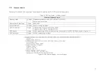
Table 3.4 Point Cloud UDP Data – Additional Information
Additional Information: 16 bytes
Reserved
5 bytes
-
High Temperature Shutdown
Flag
1 byte
0x01 for high temperature; 0x00 for normal operation
•
When high temperature is detected, the shutdown flag will be set to 0x01, and the system will shut
down after 60 s. The flag remains 0x01 during the 60 s and the shutdown period
•
When the system is no longer in high temperature status, the shutdown flag will be reset to 0x00 and
the system will automatically return to normal operation
Reserved
2 bytes
-
Motor Speed
2 bytes
speed_2_bytes[15:0] = speed (RPM)
GPS Timestamp
4 bytes
Firing time of the first laser in the first block, in units of
1 μs
Range: 0 to 71.58 minutes
Return Mode Information
1 byte
0x37 for Strongest Return mode, 0x38 for Last Return mode, and 0x39 for Dual Return mode
Factory Information
1 byte
0x42 (or 0x43)
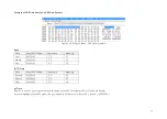
Example of UDP Data Analysis in Point Cloud Data Packets
Take Pandar40’s Channel 5 in Block 3 of the UDP Data as an example:
1)
Vertical angle of Channel 5 is 3.00°, according to Appendix I Channel Distribution
2)
Horizontal angle is the current reference angle of the rotor (Azimuth of Block 3) plus the horizontal angle offset (-2.5°, according to Appendix I).
Define clockwise in the top view as the horizontal angles’ positive direction
3)
The 2-byte distance data in the UDP Data Packet, multiplied by 4 mm, is the actual distance in real world millimeters
After determining the horizontal angle, vertical angle, and distance of a data point, this point can be drawn in a polar or rectangular coordinate system. The
real-time point cloud data is drawn by analyzing every point in the UDP data.
Summary of Contents for Pandar40
Page 1: ......
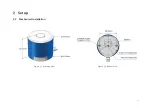
Page 9: ...5 2 Setup 2 1 Mechanical Installation Figure 2 1 Isometric View Figure 2 2 Bottom View ...
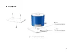
Page 10: ...6 Quick Installation Figure 2 3 Diagram of Quick Installation ...
Page 11: ...7 Stable Installation Figure 2 4 Diagram of Stable Installation ...
Page 15: ...11 2 3 2 Connection Figure 2 7 LiDAR Connection When Using the Connecting Box ...
Page 46: ......

